How to install the app on iOS
Follow along with the video below to see how to install our site as a web app on your home screen.
Note: This feature may not be available in some browsers.
You are using an out of date browser. It may not display this or other websites correctly.
You should upgrade or use an alternative browser.
You should upgrade or use an alternative browser.
JF-17 Block III's proposed AESA Radar KLJ-7A
- Thread starter cirr
- Start date

volatile
SENIOR MEMBER

- Joined
- Mar 11, 2011
- Messages
- 4,041
- Reaction score
- 1
- Country

- Location


Very interesting with Mig 21/J7 have RCS of 3 in clean configuration the choice of testing is superb Im sure the same radar will come across other platforms as well if already not done
Radar Cross Section (RCS)
RCS (m2) RCS (dB)
automobile 100 20
B-52 100
B-1(A/B) 10
F-15 25
Su-27 15
cabin cruiser 10 10
Su-MKI 4
Mig-21 3
F-16 5
F-16C 1.2
man 1 0
F-18 1
Rafale 1
B-2 0.75 ?
Typhoon 0.5
Tomahawk SLCM 0.5
B-2 0.1 ?
A-12/SR-71 0.01 (22 in2)
bird 0.01 -20
F-35 / JSF 0.005 -30
F-117 0.003
insect 0.001 -30
F-22 0.0001 -40
B-2 0.0001 -40

The radar cross section (RCS) of a target is defined as the effective areaintercepting an amount of incident power which, when scattered isotropically, produces a level of reflected power at the radar equal to that from the target. RCS calculations require broad and extensive technical knowledge, thus many scientists and scholars find the subject challenging and intellectually motivating. This is a very complex field that defies simple explanation, and any short treatment is only a very rough approximation.
The units of radar cross section are square meters; however, the radar cross section is NOT the same as the area of the target. Because of the wide range of amplitudes typically encountered on a target, RCS is frequently expressed in dBsm, or decibels relative to one square meter. The RCS is the projected area of a metal sphere that is large compared with the wavelength and that, if substituted for the object, would scatter identically the same power back to the radar. However, the RCS of all but the simplest scatterers fluctuates greatly with the orientation of the object, so the notion of an equivalent sphere is not very useful.

Different structures will exhibit different RCS dependence on frequency than a sphere. However, three frequency regimes are identifiable for most structures. In the Rayleigh region at low frequencies, target dimensions are much less than the radar wavelength. In this region RCS is proportional with the fourth power of the frequency. In the Resonance or Mie Region at medium frequencies, target dimensions and the radar wavelength are in the same order. The RCS oscillates in the resonance region. In the Optical Region of high frequencies, target dimensions are very large compared to the radar wavelength. In this region RCS is roughly the same size as the real area of target. The RCS behaves more simply in the high-frequency region. In this region, the RCS of a sphere is constant.
In general, codes based on the methods-of-moments (MOM) solution to the electrical field integral equation (EFIE) are used to calculate scattering in the Rayleigh and resonance regions. Codes based on physical optics (PO) and the physical theory of diffraction (PTD) are used in the optical or high-frequency region. The target's electrical size (which is proportional to frequency and inversely proportional to the radar wavelength) that determines the appropriate algorithm to calculate the scattering. When the target length is less than 5 to 10 wavelengths, the EFIE-MOM algorithm is used. Alternatively, if the target wavelength is above 5 to 10 wavelengths, the PO-PTD algorithm is used.
The RCS of a stealth aircraft is typically multiple orders of magnitude lower than a conventional plane and is often comparable to that of a small bird or large insect. "From the front, the F/A-22's signature is -40dBm2 (the size of a marble) while the F-35's is -30 dBm2 (the size of a golf ball). The F-35 is said to have a small area of vulnerability from the rear because engineers reduced cost by not designing a radar blocker for the engine exhaust." [Aviation Week & Space Technology; 11/14/2005, page 27] The F-35 stealthiness is a bit better than the B-2 bomber, which, in turn, was twice as good as that on the even older F-117. B-2 stealth bomber has a very small cross section. The RCS of a B-26 bomber exceeds 35 dBm2 (3100m2 ) from certain angles. In contrast, the RCS of the B-2 stealth bomber is widely reported to be about -40dBm2 .
A conventional fighter aircraft such as an F-4 has an RCS of about six square meters (m2), and the much larger but low-observable B-2 bomber, which incorporates advanced stealth technologies into its design, by some accounts has an RCS of approximately 0.75 m2 [this is four orders of magintude greater than the widely reported -40dBm2 ]. Some reports give the B-2 a head-on radar cross section no larger than a bird, 0.01 m2 or -20dBm2. A typical cruise missile with UAV-like characteristics has an RCS in the range of 1 m2; the Tomahawk ALCM, designed in the 1970s and utilizing the fairly simple low-observable technologies then available, has an RCS of less than 0.05 m2.
The impact of lowered observability can be dramatic because it reduces the maximum detection range from missile defenses, resulting in minimal time for intercept. The US airborne warning and control system (AWACS) radar system was designed to detect aircraft with an RCS of 7 m2 at a range of at least 370 km and typical nonstealthy cruise missiles at a range of at least 227 km; stealthy cruise missiles, however, could approach air defenses to within 108 km before being detected. If such missiles traveled at a speed of 805 km per hour (500 miles per hour), air defenses would have only eight minutes to engage and destroy the stealthy missile and 17 minutes for the nonstealthy missile. Furthermore, a low-observable LACM can be difficult to engage and destroy, even if detected. Cruise missiles with an RCS of 0.1 m2 or smaller are difficult for surface-to-air missile (SAM) fire-control radars to track. Consequently, even if a SAM battery detects the missile, it may not acquire a sufficient lock on the target to complete the intercept.
Radar scattering from any realistic target is a function of the body's material properties as well as its geometry. Once the specular reflections have been eliminated by radar absorbing materials, only nonspecular or diffractive sources are left. Non-specular scatterers are edges, creeping waves, and traveling waves. They often dominate backscattering patterns of realistic targets in the aspect ranges of most interest. The traveling wave is a high frequency phenomenon. Surface traveling waves are launched for horizontal polarization and grazing angles of incidence on targets with longs mooth surfaces. There is little attenuation from the flat smooth surface, so the wave builds up as it travels along the target. Upon reaching a surface discontinuity, for example an edge, the traveling wave is scattered and part of it propagates back toward the radar. The sum of the traveling waves propagating from the far end of the target toward the near end is the dominant source to the target radar cross section.
The radar cross section (RCS) of a target not only depends on the physical shape and its composite materials, but also on its subcomponents such as antennas and other sensors. These components on the platforms may be designed to meet low RCS requirements as well as their sensor system requirements. In some cases, the onboard sensors can be the predominant factor in determining a platform's total RCS. A typical example is a reciprocal high gain antenna on a low RCS platform. If the antenna beam is pointed toward the radarand the radar frequency is in the antenna operating band, theantenna scattering can be signi?cant.
The traditional measure of an object's scattering behavior is the RCS pattern which plots the scattered field magnitude as a function of aspect angle for a particular frequency and polarization. Although suitable to calculate the power received by a radar operating with those particular parameters, the RCS pattern is an incomplete descriptor of the object's scattering behavior. While the RCS pattern indicates the effect of the scattering mechanism, it does not reveal the physical processes which cause the observed effect. In contrast, imaging techniques, which exploit frequency and angle diversity to spatially resolve the reflectivity distribution of complex objects, allow the association of physical features with scattering mechanisms. These processes, therefore, indicate the causal components of the overall signature level observed in RCS patterns.
Han Patriot
ELITE MEMBER

- Joined
- Mar 23, 2011
- Messages
- 13,535
- Reaction score
- -36
- Country

- Location

Nice to know the block III is moving on smoothly.
araz
PDF THINK TANK: CONSULTANT
- Joined
- Jun 14, 2006
- Messages
- 9,291
- Reaction score
- 81
It is certainly on the cards but maybe done as a POD rather than integrated on the platform.any chance of an integrated IRST on this radar?
A
Hassan Guy
SENIOR MEMBER

- Joined
- Aug 23, 2016
- Messages
- 4,892
- Reaction score
- -3
- Country
- Location

what kind of airplanes do they use to test airbourne radars?

untitled
SENIOR MEMBER

- Joined
- Sep 13, 2008
- Messages
- 7,516
- Reaction score
- 3
- Country
- Location

An aircraft that is cheaper to operate than the original intended aircraft among other thingswhat kind of airplanes do they use to test airbourne radars?
Tempest II
PDF THINK TANK: ANALYST

- Joined
- Mar 15, 2007
- Messages
- 1,414
- Reaction score
- 11
You have to be monitoring many parameters on the functions of the radar so you have several engineers plugged in and watching. The transports offer such a platformwhat kind of airplanes do they use to test airbourne radars?
MastanKhan
PDF VETERAN
- Joined
- Dec 26, 2005
- Messages
- 21,269
- Reaction score
- 166
- Country
- Location

what kind of airplanes do they use to test airbourne radars?
Hi,
Obviously---a large one---

Shahzaz ud din
SENIOR MEMBER
- Joined
- Jun 12, 2017
- Messages
- 7,877
- Reaction score
- 14
- Country
- Location
November 25, 2017

KLJ-7A AESA radar undergoing tests with the CFTE's 711 unit. Photo source: CCTV (via East Pendulum)
Daily News
Nov 21, 2017Bilal Khan -
KLJ-7A: PROPOSED AESA RADAR FOR JF-17 UNDERGOING TESTS
ShareTweet
CCTV News footage shows that the Nanjing Research Institute of Electronics Technology (NRIET) KLJ-7A is undergoing tests with the China Flight Test Establishment’s 711 unit.
Revealed at Air Show China 2016, the NRIET KLJ-7A is a proposed AESA radar for the JF-17 Block-III, which is to be the JF-17 Thunder multi-role fighter’s most significant upgrade. The JF-17 is the mainstay fighter of the Pakistan Air Force (PAF) and is co-produced by Pakistan Aeronautical Complex (PAC) and the Aviation Industry Corporation of China (AVIC).
In comparison to current-generation mechanically-steered radars, AESA radars provide key defensibility gains against electronic warfare (EW) jamming and enemy radar detection. Instead of relying on a single array that transmits a different frequency per-single-pulse, AESA radars utilize many arrays – i.e. transmit and receive modules (TRM) – that can each transmit in a different frequency. In unison, these TRMs enable a single AESA radar unit to transmit in different frequencies simultaneously.
East Pendulum was informed by NRIET deputy director Wang Hongzhe that the KLJ-7A has a range of 170 km, though it is unclear if this is against 5m² RCS (radar cross-section) or 3m² RCS targets. It can track 15 targets and engage four simultaneously. Though equipped with 1,000 TRMs, it is not known if the KLJ-7A’s TRMs are built from gallium arsenide (GaA) or gallium nitride (GaN).
In China, NRIET is competing with AVIC’s 607 research institute – i.e. Leihua Electronic Technology Research Institute (LETRI) – for the PAF’s Block-III contract, which is expected to comprise of 50 new-built aircraft. LETRI is pitching an air-cooled AESA radar, which omits dedicated liquid-cooling systems, thereby providing valuable space and weight benefits optimal for lightweight fighter platforms.
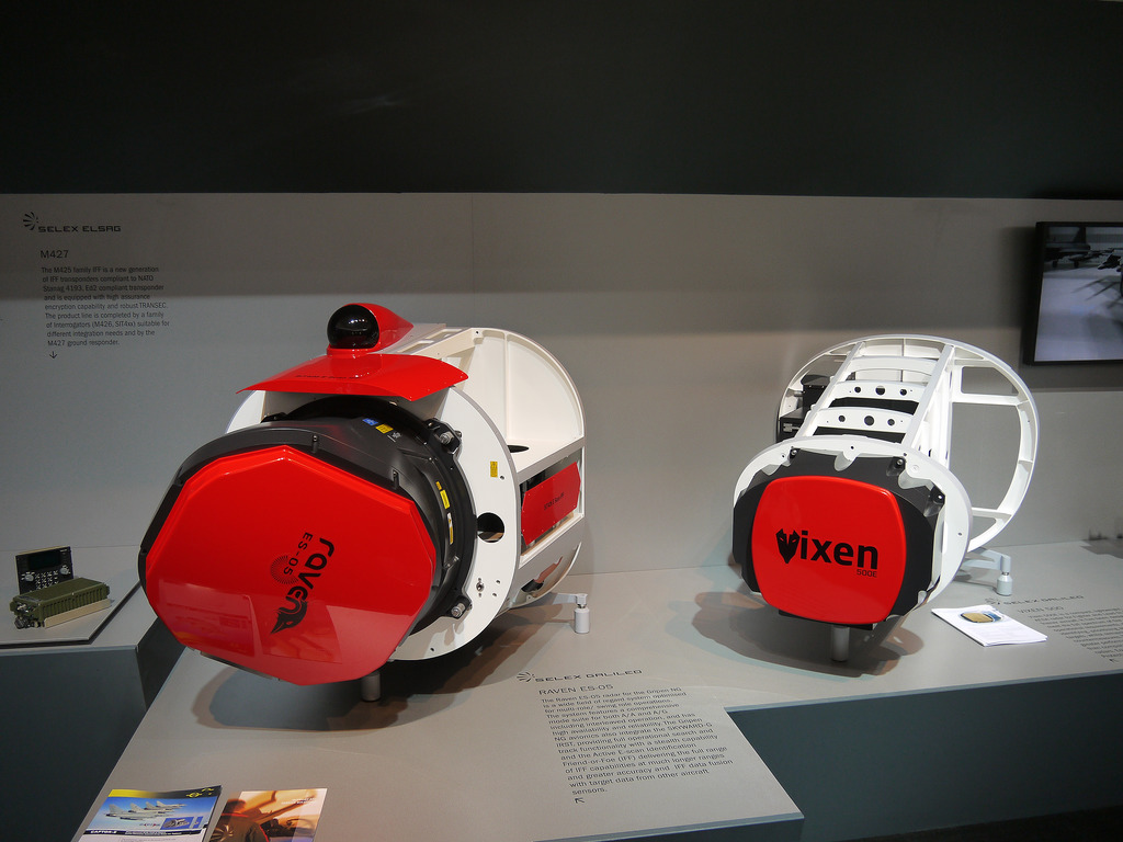
Leonardo’s Selex ES division had pitched the Vixen 1000E AESA radar as well, though industry analysts are skeptical that the PAF will select the Vixen. The PAF’s JF-17s are equipped with the SD-10 beyond-visual range (BVR) air-to-air missile (AAM) and C-802 anti-ship missile (AShM). These necessitate direct linkage to the radar for pre-terminal-stage guidance. It is unlikely that either side will cede their respective source codes to make linkage between Chinese munitions and European radars possible.
The PAF is also hoping to eventually manufacture AESA radars domestically at PAC. Proceeding with NRIET and/or LETRI for the JF-17 could set the stage for those entities to assist Pakistan in its efforts, which will be an integral aspect of Project Azm, which envisages developing and producing a 5th-generation fighter for the PAF. It is unlikely that Leonardo would be as forthcoming in this regard.
KLJ-7A AESA radar undergoing tests with the CFTE's 711 unit. Photo source: CCTV (via East Pendulum)
Daily News
Nov 21, 2017Bilal Khan -
KLJ-7A: PROPOSED AESA RADAR FOR JF-17 UNDERGOING TESTS
ShareTweet
CCTV News footage shows that the Nanjing Research Institute of Electronics Technology (NRIET) KLJ-7A is undergoing tests with the China Flight Test Establishment’s 711 unit.
Revealed at Air Show China 2016, the NRIET KLJ-7A is a proposed AESA radar for the JF-17 Block-III, which is to be the JF-17 Thunder multi-role fighter’s most significant upgrade. The JF-17 is the mainstay fighter of the Pakistan Air Force (PAF) and is co-produced by Pakistan Aeronautical Complex (PAC) and the Aviation Industry Corporation of China (AVIC).
In comparison to current-generation mechanically-steered radars, AESA radars provide key defensibility gains against electronic warfare (EW) jamming and enemy radar detection. Instead of relying on a single array that transmits a different frequency per-single-pulse, AESA radars utilize many arrays – i.e. transmit and receive modules (TRM) – that can each transmit in a different frequency. In unison, these TRMs enable a single AESA radar unit to transmit in different frequencies simultaneously.
East Pendulum was informed by NRIET deputy director Wang Hongzhe that the KLJ-7A has a range of 170 km, though it is unclear if this is against 5m² RCS (radar cross-section) or 3m² RCS targets. It can track 15 targets and engage four simultaneously. Though equipped with 1,000 TRMs, it is not known if the KLJ-7A’s TRMs are built from gallium arsenide (GaA) or gallium nitride (GaN).
In China, NRIET is competing with AVIC’s 607 research institute – i.e. Leihua Electronic Technology Research Institute (LETRI) – for the PAF’s Block-III contract, which is expected to comprise of 50 new-built aircraft. LETRI is pitching an air-cooled AESA radar, which omits dedicated liquid-cooling systems, thereby providing valuable space and weight benefits optimal for lightweight fighter platforms.
Leonardo’s Selex ES division had pitched the Vixen 1000E AESA radar as well, though industry analysts are skeptical that the PAF will select the Vixen. The PAF’s JF-17s are equipped with the SD-10 beyond-visual range (BVR) air-to-air missile (AAM) and C-802 anti-ship missile (AShM). These necessitate direct linkage to the radar for pre-terminal-stage guidance. It is unlikely that either side will cede their respective source codes to make linkage between Chinese munitions and European radars possible.
The PAF is also hoping to eventually manufacture AESA radars domestically at PAC. Proceeding with NRIET and/or LETRI for the JF-17 could set the stage for those entities to assist Pakistan in its efforts, which will be an integral aspect of Project Azm, which envisages developing and producing a 5th-generation fighter for the PAF. It is unlikely that Leonardo would be as forthcoming in this regard.
Tempest II
PDF THINK TANK: ANALYST
- Joined
- Mar 15, 2007
- Messages
- 1,414
- Reaction score
- 11
I had hoped someone with more knowledge and insight would try to count the pixels. To get the conversation going, I have had a go and hopefully someone with more experience will refine. At the moment I am coming with about 729 modules from the CCTV video of mid November 2017. What is wrong with my counting to be far off the >1,000 modules reported? Or is the prototype a "miniature" model?


Most detailed analysis I could find yet. According to it direct competitor is Vixen 1000E, so JF-17 will be fielding a radar matching the same league as Grippen NG. It also says cooling is flexible for retrofit by preserving old components, so although it is too early to say whether it will be done or not but could potentially see the same radar equipping the Block-2 & 1s if PAF desires in any future mid life update.
Ran it through google translate. Original site is in French
http://www.eastpendulum.com/klj-7a-1er-radar-embarque-aesa-chinois-dedie-a-lexport-est-en-vol
After its first public appearance at the Zhuhai Air Show last year, the KLJ-7A , China's first active electronic scanning radar (AESA) entirely dedicated to export, has disappeared from the radar screens. Its manufacturer, the Nanjing Research Institute of Electronics Technology (NRIET), better known as Institute 14 of the CETC group, also remained very discreet on the subject.
And it is in a TV report of the Chinese channel CCTV-2 , broadcast this Monday, November 20, that we learn that this radar candidate for Standard Block III of the Sino-Pakistani fighter JF-17 has in fact already entered its flight test phase.
The journalists had the opportunity to attend one of the tests that took place on November 14, when the KLJ-7A, installed on a test bench flying Y-7 , was tested on its ability to detect multiple fast moving targets over 100 km, stability of the follow-up, as well as the simulation of arms fire. Two J-7 fighters assigned to the China Flight Test Establishment (CFTE) also participated in the test to serve as a target.
The fact that these tests now take place at the CFTE also means that the Chinese on-board radar is on the final stretch before its final validation.

The two J-7s serving as targets in the KLJ-7A radar test (Image; CCTV-2)

Flying Test Bench, Registered 712, for KLJ-7A Radar Flight Test (Image; CCTV-2)

KLJ-7A Radar Test Screen (Image; CCTV-2)

The AESA KLJ-7A radar installed under the CFTE Y-7 radome (Image; CCTV-2)

KLJ-7A radar exhibited at Zhuhai Air Show 2016
Except for the details already mentioned last year in our file " Airshow China 2016: KLJ-7A, radar at AESA ", namely that it is an AESA radar with more than 1000 transmitters and receivers ( T / R), with at least 11 operating modes and a range of 170 km for targets of 5 m² SER, and able to track 15 different targets and engage 4 simultaneously, we finally could see what the KLJ-7A antennas face, which had been protected and therefore hidden during its exhibition in Zhuhai in November 2016.
Despite the quality of the images in the television report, it is assumed that the antennas are "Notch" type installed in a brick architecture, unlike the "patch" or "slot" type that has already been seen on some PESA embedded radars and Chinese AESA. This shape generates a greater beam width and also a better gain.
Although it is not T-R modules installed in 3D tile as is the case for the AESA radar J-20 hunter, but for a product dedicated to export must know how to adapt to the market and to its customers.
We also learn that the radar can be adapted to most on-board cooling systems, whether it is a system cooled in air or in liquid. This will reduce the cost of replacement on existing devices by preserving some components already installed on board.

Competitor of the KLJ-7A, the Italian AESA radar VIXEN 1000E
It is still unclear whether the KLJ-7A will be chosen by the Pakistan Air Force to equip the JF-17 Block III currently under development at the 611 Chengdu Institute in China, but it will face a significant competitor in its category which is the VIXEN 1000E , designated by the Italian Selex ES for the Swedish hunter Saab Gripen NG / E.
We should therefore relive another Sino-Italian competition as was the case between the Grifo S-7 mechanical radar and the Chinese equivalent KLJ-7 V2 at the time for the JF-17 Block I.
To be continued.
Henri K.
Ran it through google translate. Original site is in French
http://www.eastpendulum.com/klj-7a-1er-radar-embarque-aesa-chinois-dedie-a-lexport-est-en-vol
After its first public appearance at the Zhuhai Air Show last year, the KLJ-7A , China's first active electronic scanning radar (AESA) entirely dedicated to export, has disappeared from the radar screens. Its manufacturer, the Nanjing Research Institute of Electronics Technology (NRIET), better known as Institute 14 of the CETC group, also remained very discreet on the subject.
And it is in a TV report of the Chinese channel CCTV-2 , broadcast this Monday, November 20, that we learn that this radar candidate for Standard Block III of the Sino-Pakistani fighter JF-17 has in fact already entered its flight test phase.
The journalists had the opportunity to attend one of the tests that took place on November 14, when the KLJ-7A, installed on a test bench flying Y-7 , was tested on its ability to detect multiple fast moving targets over 100 km, stability of the follow-up, as well as the simulation of arms fire. Two J-7 fighters assigned to the China Flight Test Establishment (CFTE) also participated in the test to serve as a target.
The fact that these tests now take place at the CFTE also means that the Chinese on-board radar is on the final stretch before its final validation.

The two J-7s serving as targets in the KLJ-7A radar test (Image; CCTV-2)

Flying Test Bench, Registered 712, for KLJ-7A Radar Flight Test (Image; CCTV-2)

KLJ-7A Radar Test Screen (Image; CCTV-2)

The AESA KLJ-7A radar installed under the CFTE Y-7 radome (Image; CCTV-2)

KLJ-7A radar exhibited at Zhuhai Air Show 2016
Except for the details already mentioned last year in our file " Airshow China 2016: KLJ-7A, radar at AESA ", namely that it is an AESA radar with more than 1000 transmitters and receivers ( T / R), with at least 11 operating modes and a range of 170 km for targets of 5 m² SER, and able to track 15 different targets and engage 4 simultaneously, we finally could see what the KLJ-7A antennas face, which had been protected and therefore hidden during its exhibition in Zhuhai in November 2016.
Despite the quality of the images in the television report, it is assumed that the antennas are "Notch" type installed in a brick architecture, unlike the "patch" or "slot" type that has already been seen on some PESA embedded radars and Chinese AESA. This shape generates a greater beam width and also a better gain.
Although it is not T-R modules installed in 3D tile as is the case for the AESA radar J-20 hunter, but for a product dedicated to export must know how to adapt to the market and to its customers.
We also learn that the radar can be adapted to most on-board cooling systems, whether it is a system cooled in air or in liquid. This will reduce the cost of replacement on existing devices by preserving some components already installed on board.
Competitor of the KLJ-7A, the Italian AESA radar VIXEN 1000E
It is still unclear whether the KLJ-7A will be chosen by the Pakistan Air Force to equip the JF-17 Block III currently under development at the 611 Chengdu Institute in China, but it will face a significant competitor in its category which is the VIXEN 1000E , designated by the Italian Selex ES for the Swedish hunter Saab Gripen NG / E.
We should therefore relive another Sino-Italian competition as was the case between the Grifo S-7 mechanical radar and the Chinese equivalent KLJ-7 V2 at the time for the JF-17 Block I.
To be continued.
Henri K.
Last edited:
Arsalan
THINK TANK CHAIRMAN
- Joined
- Sep 29, 2008
- Messages
- 18,178
- Reaction score
- 65
- Country
- Location
Lolz,I had hoped someone with more knowledge and insight would try to count the pixels. To get the conversation going, I have had a go and hopefully someone with more experience will refine. At the moment I am coming with about 729 modules from the CCTV video of mid November 2017. What is wrong with my counting to be far off the >1,000 modules reported? Or is the prototype a "miniature" model?
View attachment 446360
I have tried and and came to conclusion that the number was OVER 1000. 27 horizontal lines in central main part, 5 lines of modules in top and 7 in bottom tapered part. Can count 30 modules in each horizontal line.
However these are jagged so some will have 4-6 modules less than other. Lets make it;
15 x 30 = 450
15 x 26 = 390
Now for top part, 7 lines, you can see there is a cut before tapered part. Will just reduce the number of modules by 10 and then gradually decrease each line by two more:
20+18+16+14+12 = 80
For bottom part, there is no cut and the taper is gradual. Will count it as:
28 + 26 + 24 + 22 + 20 + 18 + 16 = 154
Total = 450 + 390 + 80 + 154 = 1074
I know it is not very authentic way of doing it and involves some assumptions and guess work but with picture that we have, this is pretty much the best i could come up with.
This however is a very low resolution picture. If we can get a slightly better picture and/or a front on shot, it will make things easier.
@HRK @Dazzler @Bilal Khan (Quwa) @araz
Last edited:
Dazzler
PDF THINK TANK: CONSULTANT
- Joined
- Oct 19, 2008
- Messages
- 9,163
- Reaction score
- 31
- Country
- Location
Lolz,
I have tried and and came to conclusion that the number was OVER 1000. 27 horizontal lines in central main part, 5 lines of modules in top and 7 in bottom tapered part. Can count 30 modules in each horizontal line.
However these are jagged so some will have 4-6 modules less than other. Lets make it;
15 x 30 = 450
15 x 26 = 390
Now for top part, 7 lines, you can see there is a cut before tapered part. Will just reduce the number of modules by 10 and then gradually decrease each line by two more:
20+18+16+14+12 = 80
For bottom part, there is no cut and the taper is gradual. Will count it as:
28 + 26 + 24 + 22 + 20 + 18 + 16 = 154
Total = 450 + 390 + 80 + 154 = 1074
I know it is not very authentic way of doing it and involves some assumptions and guess work but with picture that we have, this is pretty much the best i could come up with.
This however is a very low resolution picture. If we can get a slightly better picture and/or a front on shot, it will make things easier.
@HRK @Dazzler @Bilal Khan (Quwa) @araz
Yep, they say it has just under 1100 modules so i guess your calculations went pretty close.
Similar threads
- Replies
- 327
- Views
- 20K