What's new

Sukhoi PAK-FA / FGFA: Updates,News & Discussions

Under the wings I believe. Or maybe it can sit inside the weapon bay,
however the bay door needs to be opened if the pod wants to
see what's happening on the ground below.

This is disappointing man.............should have been made internal
 
.
wjgemr.jpg
 
.
Sukhoi T-50 / PAK FA - official patent analysis
by IKE 29-Jan-2012 00:17

t50_6.jpg

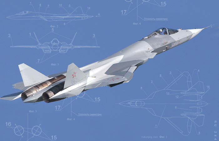
The new Sukhoi T-50 / PAK FA Russian fighter is by now quite well known but any official document is certainly welcome. That is the case of the Sukhoi patent that form the basis of this post. Even if it may not bring groundbreaking details, it presents some interesting aspects that may be quite interesting even if they are just raising speculation to fact. This patent document published just yesterday (although submitted by Sukhoi 2 years ago) by the Russian patent office. It presents the general arrangement of the new PAK-FA aircraft, it describes its aerodynamic configuration and function and also some aspects of its design concerning low radar observability. Read below for more details and images.---
t50_10.jpg


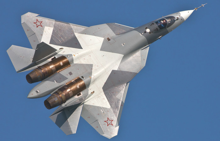
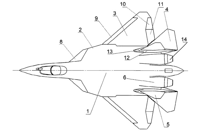
The T-50 is a substantial evolution of the Su-27 (T-10) family. It has a main trapezoid wing, all moving horizontal and vertical tails and a new kind of canard-like airfoils in front of the main wing (part 8 in the images). There are also slats, flapperons and ailerons. It is worth noting that only theT-50 along with F-22 are the only operational (or to be operational) fighters that are designed from the start with thrust vectoring. All others (ex Su-30) are adapted with movable nozzles at a later stage of their development.

The patent describes in more depth the operation and role of all aerodynamic surfaces. The fuselage is described as having ‘dogtooth extensions’ which are similar in shape and role with the leading root extensions (LERX) of many modern jet fighters and popular with Sukhoi. The fuselage houses the engine and their inlets at its edges and in between it is flattened, providing lift and also space for internal payload. The overall shape with the flat central fuselage, smoothly blended wings and integration of thrust vectoring with all movable surfaces consist what Sukhoi characterizes as integral aerodynamic design.

The wings are smoothly jointed with the flat shaped fuselage via a wide chord created by the negative sweep angle of the trailing edge of the wing. This allows for large values of absolute height especially at the root but small values of relative thickness combining good structural integrity with lower drag forces in the trans and supersonic flight.
t50_13.jpg


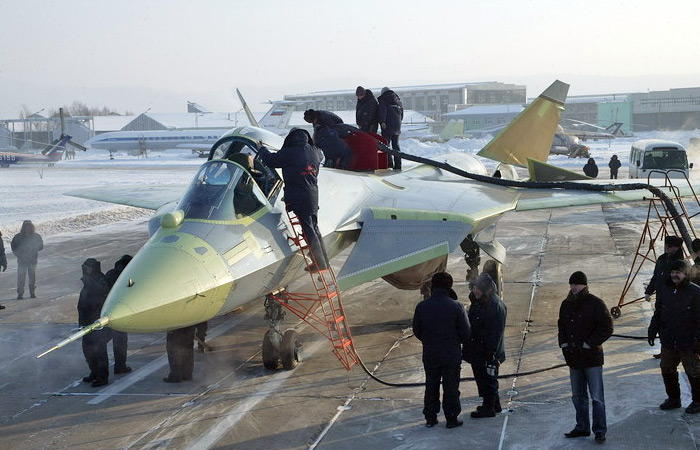
One of the most innovative features of T-50 is the movable airfoils above and in front of the inlets. They are more similar to the slats of the main wing rather than Su-30’s canards. These surfaces can rotate downwards around their rear edge. Similar to wing slats, they are rotated to assist control in high angles of attack (close to 90deg.) by reducing the exposed area to the direction of flight and also preserving lift by turning the influx over the fuselage (in a similar manner where slats have the same effect to the wing). These rotary parts shade the main engine inlets but there are auxiliary inlets at the sidewalls of the inlet tunnels where air can flow in avoiding restrictions.
t50_9.jpg


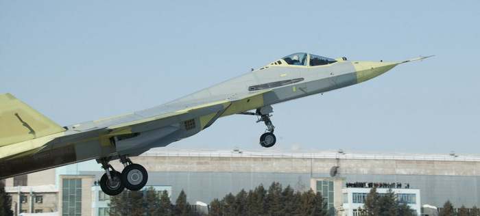
The main wing is equipped with leading edge slats and also with flapperons and ailerons. The flapperons are used in-phase as flaps in take off and landing and moving differentially as ailerons in transonic and supersonic speed. The wing outer ailerons are used only at very low speeds and at take-off/landing to control roll.

t50_8.jpg


The horizontal tail is all-moving and provides pitch control in all flight regimes by moving in-phase. At supersonic speed it also provides roll control by differential movement.

The vertical tails are also all-moving, a rather unusual approach. There are widely spaced in order to provide the necessary momentum arm but with a smaller surface. They move in-phase to provide yaw control operating as rudders and differentialy to increase drag, acting as an air brake. They are also inclined outwards to reduce the radar visibility in the lateral hemisphere.

t50_7.jpg


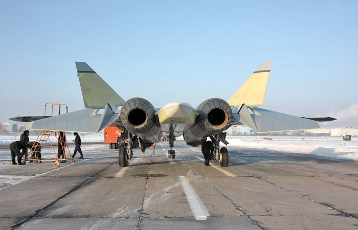
Engine placement is a crucial part of T-50’s architecture. The two engines are placed wide apart leaving space for payload between them. The air intakes are located similarly on each side of the fuselage and they are beveled in two planes in order to keep the flow attached even at high angles of attack. The air intakes are further apart in respect to the vertical and horizontal planes than the engines thus the ducts are curved. This curvature hides the compressor and reduces the radar signature of the engine in the forward hemisphere, a common practice in many recent (or not so recent) designs.

http://robotpig.net/_images/posts/t50_11.jpg

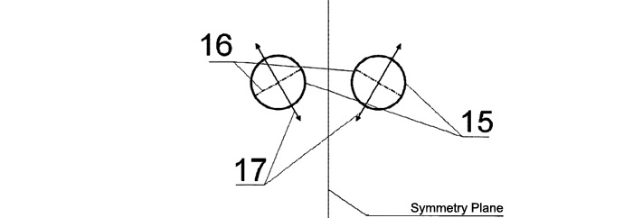
The engines are also placed at an angle relative to the vertical plane. Their nozzles are faced slightly outwards, this feature along with the significant distance between them and also the inherit use of thrust vectoring assigns a significant portion of the control of the aircraft to them. The thrust vector of each engine is used along with the aerodynamic surfaces to control the aircraft. The two nozzles can deflect the thrust vector by rotating around two axes (elements 15 and 16 at the image) either in common mode or differentially. The angle between their axis and the vertical plane can create rotating moments when different thrust is produced by each engine and also counter-acts the asymmetrical moment each engine creates because of its lateral distance from the longitudinal symmetry axis.

t50_12.jpg


The T-50 doesn’t appear to be as stealthy as F-22 an observation we have already stated in a previous post (Sukhoi T-50 - 5th gen. fighter flies). However its design is heavily influenced by low radar visibility requirements even if as the patents states that is contradicting with the demands for high (“super”) maneuverability and good flight characteristics. This document doesn’t go into great details, the T-50 has many surfaces and edges aligned together and as stated above the compressor of each engine is hidden by the curvature of the inlet path created by the inlet’s two-plane offset. Many small or bigger details found on the 3 prototypes are far removed from stealth requirements, like the nozzle shape or the various air-inlets and exhausts. However like the Su-27 that evolved greatly from the T-10 prototypes to today’s Su-35S there is room for gradual improvement, it is still too early.

You can find the full patent from Russian Patent Office in Russian (pdf) or translated. The inspiration to find this link (not very easy because we don’t speak Russian!) came from a post by “flateric” at secretprojects.co.uk forum

(images: KnAAPO/Sukhoi)

Source

man this thing is OLD as hell,,,,probably a fossil by now(this patent i mean)
 
. . . . .
some details...............anyone??

T-50_MAKS-2013_137.JPG

@Flamingo

can u translate??

T-50_MAKS-2013_139.JPG
 
Last edited by a moderator:
. .
some details...............anyone??

T-50_MAKS-2013_137.JPG

@Flamingo

can u translate??

T-50_MAKS-2013_139.JPG
@he-man I don't know T of Technicality of Fighter Plane. Therefore, it's cumbersome for me to explain everything. I'll give it an attempt in evening. I can right away tell you what's written in the Bullet Points in the 2nd Picture.:sick:
 
Last edited by a moderator:
.
@he-man I don't know T of Technicality of Fighter Plane. Therefore, it's cumbersome for me to explain everything. I'll give it an attempt in evening. I can right away tell you what's written in the Bullet Points in the 2nd Picture.:sick:

plssssssssss
 
Last edited by a moderator:
.
plssssssssss

The text of both the Pictures is Same.Heading of the article: Integrated transmission line antenna system Aist-50 N destroyer of the 5th generation

The Bullet Points:

1. Functioning Subsystem connection, Navigation, Recognition and induction.

2. Radar perceptibility lowering and aerodynamic resistance at the expense of conformal construction of all antennas.

3. Double reduction of antennas amount at the expense, using one antenna by few systems LA (?!) and by using switching-dividing and frequency separation arrangements.

4. Efficient choice of antennas with the biggest/highest power factor on the right direction.
 
.
The text of both the Pictures is Same.Heading of the article: Integrated transmission line antenna system Aist-50 N destroyer of the 5th generation

The Bullet Points:

1. Functioning Subsystem connection, Navigation, Recognition and induction.

2. Radar perceptibility lowering and aerodynamic resistance at the expense of conformal construction of all antennas.

3. Double reduction of antennas amount at the expense, using one antenna by few systems LA (?!) and by using switching-dividing and frequency separation arrangements.

4. Efficient choice of antennas with the biggest/highest power factor on the right direction.

thanks.................:cheers:
 
.
thanks.................:cheers:

There are couple of Russian Members on PDF. In future, you can Quote them for Translation, as I don't know technicalities of the Subject. Moreover. it's too Taxing and Boring :girl_wacko: Poka :wave:
 
.

Latest posts

Country Latest Posts

Back
Top Bottom