What's new

Its Official: JXX is going to test fly in the next few days

I never asserted, nor did I deny the existence of XX.
But...That is not what I asked. I do not care if you believe the JXX's existence or not. I repeatedly asked for sources that said canards are irrelevant to RCS prediction and reduction. Where are they?

All right, tell me wether a conductive surface is ‘conducive’ to surface waves?
Of course it does. Your deception so far is to impose the word and meaning of 'superconduction' and associates to what I originally said. Here is the proper definition of the word 'conducive'...

Superconductivity - Wikipedia, the free encyclopedia
When superconductive, a material has an electrical resistance of exactly zero.

Conducive - Definition and More from the Free Merriam-Webster Dictionary
: tending to promote or assist

Nothing of 'conducive' is about 'superconductivity', does it? A surface wave, by definition, cannot exist unless there is a surface. So when I said that a surface is conducive to surface waves, that does not mean I equate superconductivity with any surface. It mean exactly what the dictionary said -- to promote. But regarding the question of whether any surface can be a conductor or be conducive/conductive to surface waves, there are no shortages of popular literature using the word 'conductive' WITHOUT associating the word with 'superconductivity'...

RADIO SURFACE WAVE ANTENNA - Patent 3705407
An antenna for radio surface waves may be constructed from a conductor such as a tube or a flat plate which is an even multiple of wavelengths long.

Radio propagation - Wikipedia, the free encyclopedia
Surface modes

In this mode the radio wave propagates by interacting with the semi-conductive surface of the earth. The wave "clings" to the surface and thus follows the curvature of the earth.

Low-power radar stations enhance maritime-domain awareness | SPIE Newsroom: SPIE
HFDR exploits ducting (or tunneling) of radio waves along the conductive seawater surface.
Do you see any associations to 'superconductivity' in the examples above? We have water, ground and unnamed materials as being conducive -- promoting -- surface waves. But nothing at all about superconductivity. You need to fire whoever is coaching you in this debate. Neither of you know what you are talking about and so both of you end up grasping at this language straw in trying to prove me wrong.

Again for your easy reading, at popular science level, refer to the following article:

Electromagnetic Surface Waves

In fact, surface EM waves (SEMWs) are still not fully understood. Attempting to change the fact by being a fundamentalist just won’t work:

http://iopscience.iop.org/1063-7869/51/1/L06/pdf/PHU_51_1_L06.pdf
Just because we do not fully understood surface wave properties, that does not mean we cannot exploit it, and you have not proved I changed any facts. If anything, I have exposed more Chinese fanboys' made up 'facts' than you care to admit.

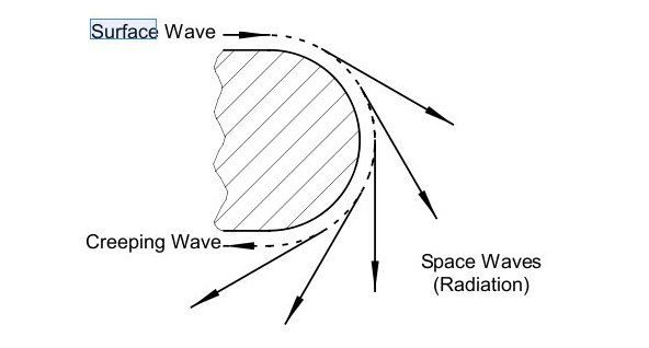
I feel really sorry that you made another joke when I asked you about the “supporting wave” in my leading questions.

There is no such thing called “supporting wave”.
The 'supporting wave' wording is YOURS. Not mine. I said that a surface wave is supported or kept alive or sustained by the power of the transmission itself, whereas the creeping wave eventually die from energy loss IF the electrical path is long enough.

Incident EM field and free electron distribution in a conductor (or polarization of the medium if not conductive) are at equilibrium instantly (in general), through the interface. They affect each other in the establishment of the EM wave around the interface and beyond. The field in the vacuum is caused by Hertz radiation of the (radar) source and by excited electrons in the medium (a good approximation is dipole approximation). If the incident wave and excited wave are in phase, the field in the vacuum(or the medium where the source is) but close to the interface will be enhanced; if they are out of phase, they’ll be cancelled. So-called Brewster’s angle Brewster's angle - Wikipedia, the free encyclopedia is when incident wave and wave excited by the dipoles in the medium happen to cancel each other completely. In this case, a radar (or whatever) detector will not get any reflection, if the polarization of the source is parallel (or is a ‘P’ wave).
If...??? :rofl: :rofl: :rofl:

Here is what the Brewster's Angle, or polarization, said...

Brewster's angle - Wikipedia, the free encyclopedia
Brewster's angle (also known as the polarization angle) is an angle of incidence at which light with a particular polarization is perfectly transmitted through a surface, with no reflection.

The polarization that cannot be reflected at this angle is the polarization for which the electric field of the light waves lies in the same plane as the incident ray and the surface normal (i.e. the plane of incidence).
In effect, you are saying that a canard should be dismissed as a factor in RCS prediction/reduction methods because of the CHANCE that a properly polarized radar transmission with respect to the canard itself will not produce any reflection. You are asking radar engineers the world over to disregard, not just the canard, but effectively ANY flight control surface as a factor in RCS prediction/reduction just on this CHANCE?

Readers,

This is what I mean about making up facts and distortions of ideas by many of the Chinese members of this forum and their exposure. The question is whether or not canards on an aircraft -- JXX -- is a contributor to its overall RCS. All the world's technical literature, derived from controlled laboratory experiments to field experience, says -- Yes. Mr. gpit so far have been unable to bring to the debate not even a single credible source that says -- No. Although two or more sources are desirable. So in order to equate the JXX to the F-22's stature, thereby also elevating Chinese aviation, he resort to the tactic of 'data mining' in breaking down a scattering point's components, of which polarization is part, and bring to the fore only the component(s) that, no matter how specious, will support his assertion or belief. Am not saying that polarization does not exist, am saying that Mr. gpit deliberately discard everything else that are at least of equal, if not more, important factors.

So according to Mr. gpit here, the JXX will analyze the seeking radar's polarization, continuously adjust its aspect angle to match, and proceed to the target totally undetected because the aircraft will not produce any reflections. Considering we are dealing with the speed of light for the radar transmission and the constant flight attitude readjustments to match polarizations by the aircraft, these Chinese pilots must be nothing short of Supermen to withstand the physical stresses.

But there is an interesting component regarding polarization that Mr. gpit conveniently omit...Anisotropic material...

Isotropy - Wikipedia, the free encyclopedia
Isotropy is uniformity in all directions. Precise definitions depend on the subject area. The word is made up from Greek iso (equal) and tropos (direction). Exceptions, or inequalities, are frequently indicated by the prefix an, hence anisotropy. Anisotropy is also used to describe situations where properties vary systematically, dependent on direction.

Anisotropy - Wikipedia, the free encyclopedia
...is the property of being directionally dependent, as opposed to isotropy, which implies homogeneity in all directions. It can be defined as a difference, when measured along different axis, in a material's physical property (absorbance, refractive index, density, etc.) An example of anisotropy is the light coming through a polarizer.

Wood is a naturally anisotropic material. Its properties vary widely when measured with the growth grain or against it. For example, wood's strength and hardness will be different for the same sample if measured in differing orientation.
Wood is an anisotropic material. Iron is an isotropic material.

Synthetic aperture radar - Wikipedia, the free encyclopedia
Radar waves have a polarization. Different materials reflect radar waves with different intensities, but anisotropic materials such as grass often reflect different polarizations with different intensities. Some materials will also convert one polarization into another. By emitting a mixture of polarizations and using receiving antennae with a specific polarization, several different images can be collected from the same series of pulses.
Composites such as those used in aviation are usually anisotropic materials. When an EM wave penetrate an anisotropic material to any degree, that portion of the wave become a 'trapped wave'. Composites can -- not must -- be stratified, meaning the different materials that made up said composite resides at different layers. Stratifications in a composite are conducive to trapped waves. I hope Mr. gpit does not associate the word 'conducive' here to 'superconductivity' :lol: Anyway...As the readers can also infer, composites are radar absorbers to some degree. Vegetation is considered anisotropic with stratifications and is a natural radar absorber to some degree.

RADAR Overview
In the context of forest vegetation mapping, the wavelength of the RADAR system will determine whether the SAR backscatter is dominated by surface scattering or volume scattering. When relatively short-wavelength (i.e. 3 cm for X-band) microwave energy interacts with the surface of the forest canopy, the energy is scattered by small-scale components of the canopy, such as the foliage and small branches. Therefore at these wavelengths the RADAR energy reflects mainly from the surface of the canopy (Figure 2). In contrast, RADAR energy with relatively long wavelengths (i.e. 74 cm for P-band) will penetrate into the canopy and reflect from large scale components composing the canopy, including large branches, stems, and the terrain surface.
The above is an excellent example of how different freqs behave in a composite with stratifications of diverse materials.

Composites also have what is called the 'permitivity matrix'...

MRS Website : The permittivity at X-band frequencies of nickel-coated graphite fibers in an epoxy matrix
In this study, we have investigated the microwave dielectric behavior of a composite formed by embedding nickel-coated graphite fibers in an epoxy matrix. Permittivities of composites in the X-band frequency range as a function of fiber concentration, fiber length, and the degree of fiber aggregation were studied. Fiber aggregation was reduced significantly by the addition of silica particles to the composite mixture before epoxy curing. Predictions from the mean field theory fit the experimental data well at dilute fiber concentrations.
At the much smaller scale in this debate, when we have a trapped wave in a composite, the different materials in the composite, with their different levels of permitivity, will alter the wave's polarization, and we have already seen how that is possible on the larger scale with vegetation. When the wave can no longer penetrate the composite, the wave will be re-radiated to free space and will most likely have an elliptical polarization, making this particular diffraction field, or scattering point, a contributor to an aircraft's RCS. But no matter what, the Brewster's Angle effect is best when the material is isotropic and the surface is STATIONARY. An aircraft is a complex body with diverse shapes and surfaces and in flight, it cannot be stationary. Of course, to Mr. gpit and his fellow Chinese members here, the JXX will be operating in an alternate universe under different laws of physics.
 
In general, if the EM frequency is <10^17 Hz, many conductors behave like an ideal conductor. In EM sense, this means free electrons only exist on the surface, not in the body of the conductor. In this case, all above statements can be applied to our radar discussion, except (yes, another except) the radar’s pulse is extremely short that it only lasts one or two wavelength. In centimeter band, it means the pulse lasts only 10^-10 second. Well, I for the moment can’t see practical use of this equipment, as (the Fourier Transformation will see) there are lots of noises due to the short duration.
:rofl: Right...That mean the world is wrong in using centrimetric radars...??? :rofl: The X-band, which is common among fighter aircraft radars, is centimetric...

Radar Bands
X band radars operate on a wavelength of 2.5-4 cm and a frequency of 8-12 GHz.
AN/APG-66 Radar System
The AN/APG-66 is a pulse doppler X-band multi-mode radar used in the F-16.

As if that is not bad enough, you are seriously confused between wavelength and pulse length. There are X-band continous wave radars on the market. A pulse means a begining and an end. The shortest pulse possible, for any freq, is one wavelength's worth, meaning one cycle. A continuous wave radar, at any freq, mean there are NO pulses. The CW radar is on a constant transmit mode. So I cannot see how in the world can you make the above paragraph with a straight face. Further...A series of pulses is called a 'pulse train' and that is how we can use the centimetric bands, despite what you think. Give it up, the hole is getting deeper for you.

Readers,

I see no need to address the rest of Mr. gpit's drivel, especially after reading that bit about the uselessness of centimetric freq. I hope he take my advice and fire whoever coaching him in this debate. Neither one of them have any clue about the subject. To recap the discussion...The JXX is supposedly with canards so it begs the question of whether or not canards will have a negative effect on the aircraft's RCS. I say that they can -- not must -- be negative factors due to them being the foremost moveable bodies and because of the diffraction fields all surfaces produce, canards can have detrimental effects.

Diffraction fields create scattering points and this was pointed out in popular media ten years ago...

2 Rival Designers Led the Way To Stealthy Warplanes - NYTimes.com
By MALCOLM W. BROWNE
Published: May 14, 1991

Mastery of diffraction control is not the only secret of stealth. Dr. Cashen of Northrop said that in addition to direct reflection and diffraction, radar echoes result from two other scattering mechanisms: traveling waves, in which a part of an airplane acts as an antenna that receives and reradiates a radar signal, and multiple scattering, in which a radar signal is diffused.

Presenting an enemy with only jagged edges that deflect radar off to the sides rather than back to the antenna is part of this technique. Mr. Rich said that everything must be saw-toothed rather than straight, even things like seams where a transparent cockpit canopy attaches to the fuselage. Engines are buried deep inside fuselages to shield the highly reflective turbine rotors from radar, and the lips of air intakes, normally highly visible to radar, must be concealed. Engine exhausts, which are radar targets as well as attractants for infrared-guided missiles, are also concealed.

surface_wave_types.jpg


In the above example, the creeping wave is a form of surface wave. The surface area is called the electrical path. If the electrical path is sufficiently long, the creeping wave eventually die, else the creeping wave will return to source direction. The original surface wave, on the other hand, with the original radar transmission behind it, even though it will continue to lose energy due to radiation or surface impedance or even absorption, as long as those losses are not greater than the radar transmission itself, this original surface wave will not die. These are not made up facts but the truth in plain layman language.

knife_edge_diffract.jpg


airfoil_waves.gif


In the above example, we are looking at an airfoil in the motion familiar with flight, either in the horizontal or vertical axis. As the aspect angle changes, deflections are created and at the airfoil's trailing edge, we have the 'knife edge' diffraction effect. Diffraction fields are scattering points. With multiple flight control surfaces creating many diffraction fields, the scattering points can merge as destructive interference or constructive interference. The latter will contribute to the aircraft's total RCS. There will be some reflections on the leading edge that will return to source direction, they are called 'specular reflections'.

Scattering points from diffraction fields are serious enough to warrant a major design factor for the B-2...

b-2_edge_diffract.jpg


The goal is to redirect those trailing edge scattering points away from transmission direction as much as possible, hence the 'saw tooth' pattern for the aircraft itself. Whatever diffraction field signals the seeking radar may receive, the energy level would be so small that the radar would dismiss them as part of the clutter environment. The flying wing's low RCS proved itself in controlled laboratory experiments and eventually as the B-2 itself.

Repeated requests to Mr. gpit to provide at least a couple of credible sources that will categorically reject canards, or the diffraction fields they create, as irrelevant factors have gone unanswered. Instead we are given absurd claims that defied the known laws of physics and opinions, like the one about centimetric freqs, that can be easily refuted by current practices.
 
gubbi...understand that my post already explained leave it to China they are working on something days years you will come to know do you understand simple english?

don't justify you wrong assessment afterwards you've blundered already, make things clear in you initial posts so to save yourself from embarrassment on an International defense forum. That was really poor way of explaining "Stolen airframes" how can you make someone get to your context of explaining about "stolen airframes". Copying is not stealing air frames. Read my post no where did I say J-11 is new design..
copypaste grandpa aka gambit is on my ignore list for the past 5 months and will remain ignored. whether Chinese have their hands on something or not only Chinese defense insiders know not even that grandpa gambit is aware of what Chinese have or are acquiring legally or illegally..Now next time be clear in your posts..
:lol: You cannot ignore me. You can chose not to respond to me but you cannot ignore the contents of what I post. Still...Anyone who is 'ignored' by you should take it as a mark of pride that their arguments are over your head.
 
...

airfoil_waves.gif


In the above example, we are looking at an airfoil in the motion familiar with flight, either in the horizontal or vertical axis. As the aspect angle changes, deflections are created and at the airfoil's trailing edge, we have the 'knife edge' diffraction effect. Diffraction fields are scattering points. With multiple flight control surfaces creating many diffraction fields, the scattering points can merge as destructive interference or constructive interference. The latter will contribute to the aircraft's total RCS. There will be some reflections on the leading edge that will return to source direction, they are called 'specular reflections'.

Scattering points from diffraction fields are serious enough to warrant a major design factor for the B-2...

...

:rofl:

Is the picture about EM wave scattering off an airfoil?

It doesn't even looks like that. Are you sure what you are talking about? :lol:

Stop showing off your stupidity in public!

I waste too much time with this fool. FK off! :taz:

THE VELOCITY FIELD

This animation shows again the flow field, now described in terms of thr velocity vectors.

provec.gif


FLOW AROUND AN AIRFOIL - 2
 
Last edited:
:rofl:

Is the picture about EM wave scattering off an airfoil?

It doesn't even looks like that. Are you sure what you are talking about? :lol:

Stop showing off your stupidity in public!

I waste too much time with this fool. :taz: FK!
It is to visually demonstrate for the readers where you failed -- EPIC fail -- at that. Am going to ask you again...Where are your sources to say that diffraction fields from canards are irrelevant? Me stupid? Coming from someone who mixes up wavelength with pulse length...??? Give us all a break from your stupidity.
 
I have to agree that this guy has blatantly played foolhardiness to an extreme shamelessness.

Evidence 1): He clownishly claimed host water would cause surface wave the same or similar as EM would on medium interface. :rofl:

Evidence 2): He clownishly claimed EM surface wave would not dissipate its energy on the interface. :rofl:

Evidence 3): He clownishly claimed airflow velocity distribution around an airfoil could be used to demonstrate EM scattering field around an airfoil. :rofl:

Evidence 4): He pitifully has zero knowledge about the relationship between pulse duration, speed and wavelength of EM wave in a medium. :rofl:

This guy also proved himself to be a blatant liar:

a) He failed to point out where I declared that canards do not contribute to EM scattering. :devil:

Conclusion: initially I thought he probably had some high school education but either never attended college or failed in earlier years of college. Now it seems that he&#8217;s not event mastered his high school materials: he doesn&#8217;t know even the law of energy conservation. He doesn&#8217;t even know what it is &#8220;inhomogeneity&#8221;.

I feel bad for the United States Army if this guy is indeed serving in the army. No wonder the Army failed in Korea first, then in Vietnam second, then has been bogged down in Iraq and Afghanistan now. One word: Too many fools in the Army who believe just being fundamentalist or otherwise jingoist can resolve problems.


Now final question to this &#8220;expert&#8221; or otherwise &#8220;professional&#8221;: can we use airflow velocity distribution to demonstrate EM field distribution? :lol:

If yes, what if the airfoil is palced in vaccum. :woot: :lol:
 
:rofl:

Is the picture about EM wave scattering off an airfoil?

It doesn't even looks like that. Are you sure what you are talking about? :lol:

Stop showing off your stupidity in public!

I waste too much time with this fool. FK off! :taz:
If you can show everyone a better graphics demonstrating what is under discussion, do so. Else FK off...Fool...!!!
 
a) He failed to point out where I declared that canards do not contribute to EM scattering.
But that is not what I asked. Am asking you to provide a source that says diffraction fields, as scattering points, do not matter in RCS prediction and reduction techniques. Where...???
 
I have to agree that this guy has blatantly played foolhardiness to an extreme shamelessness.

Evidence 1): He clownishly claimed host water would cause surface wave the same or similar as EM would on medium interface. :rofl:

Evidence 2): He clownishly claimed EM surface wave would not dissipate its energy on the interface. :rofl:

Evidence 3): He clownishly claimed airflow velocity distribution around an airfoil could be used to demonstrate EM scattering field around an airfoil. :rofl:

Evidence 4): He pitifully has zero knowledge about the relationship between pulse duration, speed and wavelength of EM wave in a medium. :rofl:

This guy also proved himself to be a blatant liar:

a) He failed to point out where I declared that canards do not contribute to EM scattering. :devil:

Conclusion: initially I thought he probably had some high school education but either never attended college or failed in earlier years of college. Now it seems that he’s not event mastered his high school materials: he doesn’t know even the law of energy conservation. He doesn’t even know what it is “inhomogeneity”.

I feel bad for the United States Army if this guy is indeed serving in the army. No wonder the Army failed in Korea first, then in Vietnam second, then has been bogged down in Iraq and Afghanistan now. One word: Too many fools in the Army who believe just being fundamentalist or otherwise jingoist can resolve problems.


Now final question to this “expert” or otherwise “professional”: can we use airflow velocity distribution to demonstrate EM field distribution? :lol:

If yes, what if the airfoil is palced in vaccum. :woot: :lol:

Excellent scientific critique.
 
Gambit bro.leave it. .propoganda doesnt hv the source . .he cant post the source based on physics but yaa fanboys can post several photoshop images of jxx.. braging out the yet anothr propaganda..
 
Back
Top Bottom