Aerial Target
Conceived late in 1916, this was a radio-controlled, pilotless aeroplane intended both for defence against Zeppelins and as a flying bomb. In the former role it was planned that it would be controlled from the ground, but in the latter role control from an accompanying manned aeroplane was also considered. To disguise its intended purpose it was always referred to as the Aerial Target.
Its wireless apparatus was designed by Capt Archibald M Low of the RFC's wireless unit at Feltham, whose idea it was. His attempt to build the aeroplane himself, largely from spare parts, had met with no success, and the assistance of the Royal Aircraft Factory had therefore been requested. The project was undertaken by Henry Folland, although much of the detail work was drawn by his assistant, H E Preston. The Farnborough design was a small shoulder-wing monoplane powered by a two-cylinder ABC Gnat of 35hp, with numerous radio aerials running vertically down the fuselage sides and chordwise across the wings. In the interests of simplicity, lateral control was by wing warping, and generous dihedral ensured lateral stability.
Six examples, A8957-A8962, were constructed, the first being delivered to RFC Northolt, where the trials were to take place, on 5 June 1917. The intention was that the machine should be trimmed to take off and climb away to a reasonable height before radio control was attempted. Extensive windtunnel tests on models had indicated what the necessary tailplane incidence should be, but the first flight, on 6 July, consisted of an almost vertical climb away from the launching rail, followed by the inevitable stall and consequent crash, before the radio control system could take effect. It was clear that the still imperfectly understood aerodynamic differences between scale models and full-sized aeroplanes had resulted in insufficient tailplane incidence.
A second example was tested on 25 July but failed to take off, merely running along the ground until its undercarriage finally collapsed, the tailplane adjustment having been somewhat overcorrected. A third attempt, with the tailplane finally set at the correct angle, was made three days later, but unfortunately resulted in yet another crash when the engine failed just after take-off. Although damage was confined to a broken propeller and some easily repaired undercarriage components, official interest in the project appears to have diminished and no further trials are recorded as having taken place, although the project was resurrected briefly in the early 1920s.
One example was later converted to a manned aeroplane by No 3 (Western) Aircraft Depot at Bristol, and was fitted with a wheeled undercarriage and ailerons. As a rebuilt aircraft it was allotted a serial number from a batch allocated for that purpose. It received the number B8962, with numerals similar to those of its original, uncertain identity, and this has caused much ill-founded conjecture among latter-day historians.
By 1934 it had been disposed of, and was owned by Mr Ron Shelley of Billericay, but it was broken up without appearing on the civil register.
Dimensions:
span 22ft 0in; length 20ft 4in; height 5ft 10 1/2in;
chord 5ft 2in; incidence 6°; dihedral 5°.
Weight 500lb.
RAF Aerial Target / AT
The Predator's Ancestors - UAVs in The Great War
Recently, drones, or UAVs (unmanned aerial vehicles) like the Predator, Reaper, Global Hawk and Grey Eagles, have been making front page news; from bombing terrorist leaders out of existence, and surveillance of the nation’s borders, to more mundane tasks such as tracking wildfires, or analyzing traffic flow on many streets, roads, and highways across the country. Whether you agree or disagree with their usage, UAVs have a history that dates back over one hundred fifty years.
The first military use of an unmanned aerial vehicle actually occurred on August 22, 1849, when, after months of secret trial and error, the Austrians launched explosive-laden unmanned balloons over the Italian city of Venice. The Austrian military had instructed that “in favorable winds, the balloons will be launched and directed as near to Venice as possible, and on their being brought to vertical positions over the town; they will be fired by electro magnetism by means of a long isolated copper wire with a large galvanic battery placed on the shore. The bomb falls perpendicularly and explodes on reaching the ground.' Many of the balloons were launched from the Austrian ship Vulcano, but the erratic winds caused a number of the balloons to drift back over the Austrians, preventing their use, and the operation was not considered a success.
Although balloons do not generally meet today's definition of a UAV, the concept was strong enough that once winged aircraft had been invented, the effort to fly them unmanned for military purposes was not far behind. And so the story picks up again in 1916 at the height of World War One.
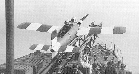
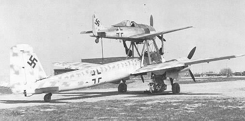
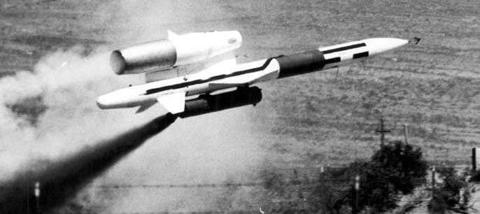
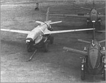
Serbian-American inventor and engineer Nikola Tesla had described a fleet of unmanned aerial combat vehicles in 1915 and the idea came to fruition in Great Britain with the “Aerial Target” (as seen in the photo at the very top.) This radio-controlled, pilotless aeroplane was intended both for defense against Zeppelins and as a flying bomb. In its role as a Zeppelin-killer, it was planned to be controlled from the ground, but as a flying bomb, the control was to be from an accompanying manned aeroplane.
The wireless apparatus was the brainchild of Capt. Archibald M. Low of the Royal Flying Corp. As a civilian, Low had written a brief based on his research to remotely control an aircraft to use as a guided missile. When the war broke out, Low joined the military and went through officer training. In just a few months he was promoted to Captain and sent to the Royal Flying Corp. With two other officers assisting him, Low set to work to see if it was possible. This project was called the "Aerial Target" or AT, a deliberate misidentification meant to fool German spies into thinking the British were building a drone aircraft to test anti-aircraft capabilities. Capt. Low attempted to build the aeroplane himself from spare parts but met with no success, and the assistance of the Royal Aircraft Factory was subsequently requested. The project was undertaken by Mr. Henry Folland, (although a considerable amount of the detail work was done by his assistant, H. E. Preston.) After a prototype was constructed, the Royal Flying Corps Experimental Works was created to build the first proper "Aerial Target" complete with an explosive warhead. Low was promoted to head up the Experimental Works and acquired about 30 picked men, including jewelers, carpenters and aircraftsmen in order to get the pilotless plane built as quickly as possible. Construction commenced at the Ruston Proctor Works where they were already building aircraft designed by the Sopwith firm.
The Ruston Proctor Works where early ATs and Sopwith aircraft were built
The aircraft design was a small shoulder-wing monoplane powered by a two-cylinder ABC Gnat engine of 35hp, with numerous radio aerials running vertically down the fuselage sides and chord-wise across the wings. In the interests of simplicity, lateral control was by wing warping and generous dihedral ensured lateral stability. Radio guidance equipment was developed and installed on the design. The first trial was held on March 21, 1917 near the Salisbury Plain in southern Britain and was attended by about forty Allied Generals. The AT was launched from the back of a lorry using compressed air and successfully demonstrated the ability to be remotely controlled before an engine failure led to a crash landing.
Contemporary artwork of what the Aerial Target looked like
Six examples, numbers A.8957 to A.8962, were constructed, the first being delivered on June 5, 1917 to the RFC base at Northolt. The intention was that the machine should be trimmed to take off and climb away to a reasonable height before radio control was attempted. Wind-tunnel testing on models had indicated what the necessary tailplane incidence should be, but the first flight on July 6th consisted of an almost vertical climb away from the launching rail, followed by the inevitable stall and crash, due to insufficient tailplane incidence and long before the radio control system could take effect.
Awaiting testing of one of the Aerial Targets in 1917
A second example was tested on July 25th but failed to even get off the ground, merely running along the ground until its undercarriage finally collapsed. This time it was determined that the tailplane adjustment had been vastly overcorrected. Three days later, a third attempt was made, with the tailplane finally set at the correct angle. Unfortunately, it resulted in yet another crash when the engine seized just after take-off. Although damage was confined to a broken propeller and some easily repaired undercarriage components, official interest in the project vanished and no further trials are recorded as having taken place. At a later date an electrically driven gyro was added to the plane, but ultimately the "Aerial Target" project was not followed up because short-sighted military leaders thought it had limited military potential.
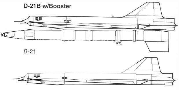
Three-view drawing by the Royal Aircraft Factory of the Aerial Target
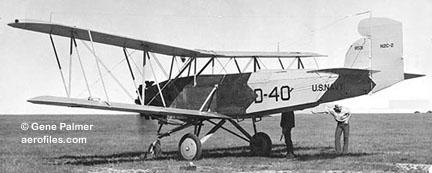
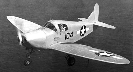
In the U.S., the Hewitt-Sperry Automatic Airplane, called the "flying bomb" made its first flight on September 12, 1917, demonstrating the concept of an unmanned aircraft. They were intended for use as "aerial torpedoes", an early version of a cruise missile.
(Germany had actually already developed a type of cruise missile; the Siemens Schuckert glider bomb or torpedo glider.) Control was achieved using gyroscopes developed by the Sperry Gyroscope Company. In November, the Automatic Airplane was flown for representatives of the U.S. Army. This led the army to commission a project that eventually resulted in the Kettering Bug which first flew in 1918. While the Bug's revolutionary technology was successful, it could not be fully developed and deployed before the war ended.
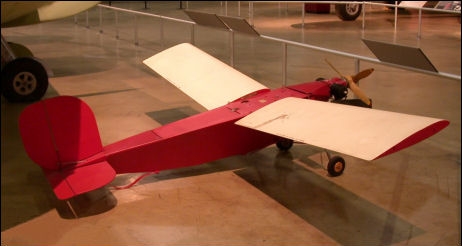
the Kettering Bug
Warnepieces: The Predator's Ancestors - UAVs in The Great War
Remote Piloted Aerial Vehicles : The 'Aerial Target' and 'Aerial Torpedo' in Britain
The 'Aerial Target' and 'Aerial Torpedo' in Britain
Aerial Torpedo.
http://www.geocities.com/jjnevins/pulpsa.html
The Aerial Torpedo was introduced in the 1909 film
The Airship Destroyer. An unknown country arms their zeppelins with bombs and launches an air raid on England. After a bombing raid British aircraft engage the zeppelins but are shot down. The bombing raid continues until finally a patriotic British inventor creates an "aerial torpedo," controlled by "wireless electricity," which he uses to bring down the enemy air fleet.
Airship Destroyer, The (Silent, England, 1909)
http://spot.colorado.edu/~dziadeck/airship/htmls/films.htm
A quickie about a zeppelin raid. The model work was very obvious. To quote from a movie list:"Inspired by Wells, this is one of the first real science fiction films to be made in England. The story concerns an attack on London by a fleet of airships from an unknown country. Through the extensive use of models, buildings were wrecked, prototype tanks destroyed, and railroads blown up. However, the films young hero, an inventor, launches radio controlled aerial torpedoes at the airships, and saves the day." The film was a great success, and was directed by Walter Booth, produced by Charles Urban.
There were 2 sequels to this film "The Pirates of 1920" (1911) and "The Aerial Anarchists (1911).
Entry in the Internet Movie Database
Airship Destroyer, The (1909) Directed by Walter R. Booth Genre: Short, Also Known As: Aerial Torpedo, The (1909) (UK) Battle of the Clouds, The (1909) (UK) Country: UK Black and White Silent
The Flying Torpedo
Silent Era : PSFL : The Flying Torpedo (1916)
(1916) American
B&W : Five reels
Directed by John B. O'Brien + [William Christy Cabanne]
Cast: John Emerson, Spottiswoode Aitken, William E. Lawrence (W.E. Lawrence), Fred J. Butler, Raymond Wells, Lucille Younge, Erich von Stroheim, Peggy Pearce (Viola Barry), Bessie Love, Ralph Lewis, Juanita Horton
Fine Arts Film Company production; distributed by Triangle Film Corporation. / Scenario by Robert M. Baker and John Emerson Production supervised by D.W. Griffith. Music score arranged by J.A. Raynes. / © January 31, 1916 by Triangle Film Corporation [LP8297]. Released March 12, 1916. / Standard 35mm spherical 1.37:1 format. / Working title: The Scarlet Band. Project began shooting in July 1915. Cabanne directed the battle sequences.
Drama: Science fiction.
Synopsis: US West Coast is invaded in 1921 by Asians and fought off by torpedoes controlled by wireless transmitters.
July 28, 1914
Dispatch Archive
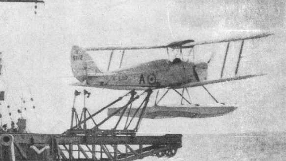
On July 28, 1914, the first aerial torpedo was launched from a Royal Navy Short seaplane by Lt. A. M. Longmore. The U. S. Navy first experimented with aerial torpedoes in late 1917, when a 400-pound dummy torpedo was dropped from a seaplane and ricocheted back into the air, almost hitting the plane.
Since the aircraft of the day could lift only about 600 pounds of bombs or other ordnance, and the normal shipboard or submarine torpedo weighed 1,500 pounds or more, the torpedo bomber was not yet a reality.
Professor A.M. Low and the 'Aerial Target'
http://naarcee.bizland.com/feedback.htm
Prior to World War One there was one man in England who was working on a brand new concept, radar. It also seems that somebody at the War Office felt that too many of England's best and brightest pilots were being killed by the Fokker Mono Plane (Eindecker) Scourge. The man who was to head up this new research project was a Professor A.M. Low.
 Sopwith AT
At the start of W.W.I Professor Low was actually working on the very first electronic range finder, based on the principles of radar, for the Artillery Corps but the RFC (Royal Flying Corps) had other things in mind for the good Professor. The RFC wanted Prof. Low to put his knowledge of radar to use in designing and developing remotely controlled pilot-less aircraft.
The concept was to develop a small, very simple aircraft. Pack it with explosives and then guide it into a designated target. Thus the RFC Experimental Works were born and the newly commissioned Second Lieutenant Low began his secret work in a Chiswick garage. As it turns out the aircraft design was the least of the challenges; it was the radio gear that needed to be developed first.
As Low made progress with the radio gear there was a need to relocate the operation to a more aeronautical site and Brooklands was chosen. It was here that it was discovered that the uncowled 50 hp Gnome rotary engine caused so much radio noise as to make the operation of the gear unreliable (sound familiar). In spite of the engine noise and unreliability of the aircraft it was shipped off to the Central Flying School at Upavon. It was subsequently never flown.
The key here is that the radio gear did operate as planned when the power plant was not running. As a matter of fact this remotely piloted vehicle (RPV) concept caught the interest of the great Sopwith Co. as well as Ruston Proctor & Co. Ltd who began immediate, parallel development to Low's own at the RFC. Granville Bradshaw of A.B.C. Motors Ltd. who gained fame by designing the well proven 45 hp Gnat engine subsequently designed a throwaway engine specifically for use in the RPV.
The 35 hp was a horizontally-opposed twin cylinder engine with a run life of 2 hours. It was this lightweight inexpensive engine that propelled RPV research and development into the next phase. In the mean time Sopwith had developed the 14ft wingspan "Sopwith AT" (AT = air target) which was fitted with the 35 hp ABC engine driving an ordinary wooden propeller. The radio box was further back towards the tail behind the fuel, batteries and of course the explosives.
The sensitive radio equipment was fitted into a wooden box with a glass lid, suspended on rubber supports. The box itself measured about 2ft 3in by 9in. This box contained all of the relays, receiver and the Key system which was an interference filter. An interesting note here, a shaft which was driven by the engine triggered a mechanical relay so that each contact made in the control box caused the engine power to operate the control services. The date was 1916 and the Sopwith AT was completed with full servo control. It never flew because it was subsequently damaged while in hangar and abandoned (sound familiar?).
The ironic end result was the creation of the Sopwith Sparrow which was a small, single seat aircraft which did in fact have a pilot after all. Naturally this is not the end of our story, enter Geoffrey de Havilland. De Havilland built a little mono plane around the lightweight ABC expendable engine. It is believed that it was the de Havilland monoplane which flew on a March 21st, 1917 test flight at Upavon. The rumor is that high ranking officials were invited to attend and were quickly dispersed in a rather comical fashion when the initial test flight went awry as they so often do. No more is known.
Later that year H.P. Folland the designer of the S.E.5 fighter embarked on task to build an aircraft using Low's radio equipment. By July of 1917 he had 5 aircraft ready for flight and on July 6, 1917 the first flight was conducted. The aircraft rolled smoothly along on a 150 ft launch track and became airborne mid way. The craft rose steeply, stalled and plummeted to the ground (sound familiar?). Two more tests were conducted on July 25 and 28 but the aircraft were under controlled and the entire "R/C" program slowed to a trickle until the end of the war.
Late in the War there was some research and development in the U.S. but it was relegated to gyroscopically controlled flying bombs and as such do not merit discussion here. It wouldn't be until September 3rd, 1924 when we would see the very first successful radio control flight of a lighter than air craft. From the decks of H.M.S. Stronghold a 23 ft wings span craft designated the RAE Target made a fully controlled 12 minute flight. The only reason why the flight ended was because the engine stopped (sound familiar ?). Success at last!
Subsequent flights off of the Stronghold were proving the viability of the notion of Radio Controlled flight. In fact the duration of the 10th flight was 39 minutes long. The flight was so successful that the RAE recorded a record 43 separate commands. Once the news of this reached the powers that be the RAE was given the go ahead to do what comes naturally...build it bigger and better with a larger pay load.
Thus the LARYNX was born. This mid- winged mono plane was designed to hold 250lbs of high powered explosives and travel a distance of over 300 miles. The Armstrong Siddeley Lynx - 200 hp engines was enclosed in a low drag cowling at the front end of a light weight tubular fuselage and attained the impressive speed of over 190 mph in the year - 1927.
This aircraft was years ahead of its kind and was even faster than its contemporary, manned, fighter planes. When it came time to actually replace the empty payload section with the intended explosives and field test the "flying bombs" they decided to forgo the R/C and install gyroscopes. They sent these aircraft to Iran where all of them failed miserably except one. This aircraft sailed off into the distance never to be seen or heard from again (sound familiar?). Whether the payload exploded or not, no one will ever know.
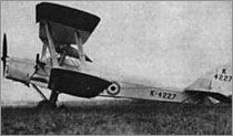
The Queen Bee
De Havilland
Tiger Moth, Two seater bi plane trainer of the Royal Air Force, Maximum speed 109 mph, Ceiling 14,000 feet, and can remain airborne for three hours. The Royal Air Force last Bi Plane, which served as a trainer from 1932 to 1947.
 Remote piloting a Queen Bee
Its design remained nearly the same throughout its history, and was well constructed and able to do aerobatics. A total of 8800 Tiger Moths were built
which included 420 Radio Controlled Pilotless Target aircraft. (The Queen Bee) for the Royal Air Force. It was also used for a short period during the first months of world war two for coastal reconnaissance.
Kálmán Tihanyi
In the beginning of 1930, Kálmán Tihanyi moved to London at the invitation of the British Air Ministry to build a prototype of his aerial torpedo, whose plans he had completed in Berlin. Later that same year, he learned of RCA's interest in his television patents. While working on the aerial torpedo and negotiating with RCA, he conducted negotiations regarding various other inventions as well: wide-screen and stereo film, a reflector for submarines, etc.
At the end of 1931, Tihanyi was invited by the Italian Navy to develop his torpedo for marine use. During the next three years, he divided his time between the laboratories of the Air Ministry in London and the laboratories of the Italian Navy off the harbor of Genoa, on Isola Castagna.
also...
In an article, entitled, "Etwas uber das Fernsehen," ("About television,") written by Kálmán Tihanyi and published in the journal:
Funk und Fernseh Technik, Berlin, (undated, but judging form reference to the invitation by the British Air Ministry to London, probably in early 1930) Tihanyi describes his Aerial Torpedo as a device which also possesses "eyes" with the help of which it "sees" and locks onto moving targets deploying one of various weapons it carries for the target's destruction. It should be noted that the patent [K. Tihanyi: Br. Pat. 352,035/December 21, 1929 application, (conv. date December 16, 1929, Hungary), issued June 22, 1931.] describes television guidance through specially constructed light and heat sensitive photocells for other types of weaponry, such as tanks, bombs, etc. as well.
http://www.scitech.mtesz.hu


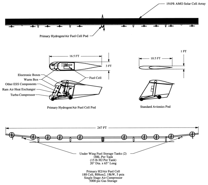


Sino-Waverider+at+Beijing+Aviation+Museum+unmanned+scramjet+demonstration+aircraft+for+hypersonic+(Mach+6,+approximately+4,000+miles+per+hour+(6,400+kmh)+at+altitude)hypersonic++(1).jpg)
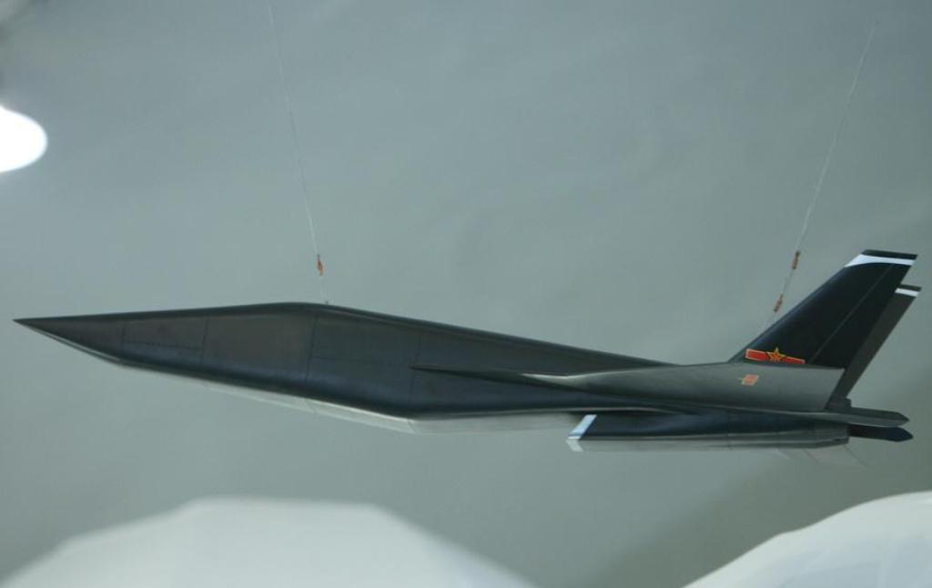


")