What's new

Japan Defence Forum

Given the rapid pace at which China is developing it's Armed Forces ,especially the Air Force and the Naval Air Arm, I thought it would be pertinent at this juncture to start a thread that specifically caters to the Japanese Air Force and Aerospace Capabilities.
 
What is the JASDF (Japanese AirSelf Defense Force) ?

JASDF was established on July 1, 1954 when the Defense Agency replaced the Security Agency, in order to bear the defense mission of Japan. Of the Ground Self-Defense Force (JGSDF), Maritime Self-Defense Force (JMSDF), and Air Self-Defense Force (JASDF), JASDF is the most recent department. There are 47,097 Self-Defense officials and 3,227 administrative officials for a total of 50,324 persons (as of the end of 2013).

Many different organizations are organized to work together in order to reliably carry out the mission "Defense".
J1.JPG


The MInistry of Defense and Self-Defense Force, centering on the armed organizations of the Ground, Maritime, and Air Self-Defense Forces, are organized with various organizations such as National Defense Academy, National Defense Medical Collage, National Institute for Defense Studies, Technical Research and Development Institute, Equipment Procurement and Construction Office, and Inspector Generals Office. JASDF established the "Air Staff Office" in Ichigaya, Tokyo. The "Air Defense Command" is the main force formation for air defense and covers all of Japan. Furthermore, other organizations, such as "Air Support Command" handling transportation, "Air Training Command" for education, "Air Developing and Proving Command" involved in aerial technique development, and "Air Material Command" in charge of the supply of equipment and commodities, are organized to work together to accomplish each mission.

Air Staff Office
The Air Staff Office is the chief organization for military service operations and includes the Chief of Staff of JASDF and his assistant agency. It works under the staff of the Minister of Defense.

Air Defense Command
The Air Defense Command is the first-line troop to be given an air combat mission. It consists of the Air Defense Command, Air Defense Force and other directly controlled forces, in order to carry out command and operations in an integrated manner.

Air Support Command
The Air Support Command is the organization to support the Air Defense Command by carrying out air strategy. In addition to the headquarters, it consists of troops for air transportation, air control, weather, and maintenance.

Air Training Command
The Air Training Command is the organization that provides education to SDF members in an integrated manner, and the educational agency to carry out basic education and training, and teach expertise and skill necessary for a SDF member.

AirDeveloping and Proving Command
The Air Developing and Proving Command is the organization for the development of the ever-changing experimental aircraft and equipment, aeromedicine, human engineering, and to carry out a wide range of research.

Air Material Command
The Air Material Command of JASDF is the organization to control supply depots No.1, No.2, No.3, and No.4 of JASDF, and is in charge of the procurement, safe-keeping, recruitment, and maintenance of necessary fuel, ammunition, and equipment.

Other Units and Organizations
In addition, there are other units and organizations such as the "Air System Communications Squadron", "Air Central Musical Band", "Air Staff College of JASDF ", "SDF District Hospitals in Misawa, Gifu, and Naha", etc.

What is JASDF? | [JASDF] Japan Air Self-Defense Force

The mission of JASDF can be summarized into the following 3 points.

Air Defense
"Air Defense" guards the nation and its territory from an incursion by air, in airspace as far from the national territory as possible. Serious damage is inflicted on the enemy, thereby making an enemy attack from the air difficult to continue.

Response to Various Situations such as Major Disasters
When an emergency such as major disaster occurs, JASDF collaborates with each prefecture, and carries out aerial reconnaissance, dispatch of necessary personnel, transportation of people and material supplies, etc.

Establishment of a Secure Enviroment
The Self-Defense Force supports efforts towards international peace through international peace cooperation works. Also, by promoting international cooperation through international disaster relief activities, etc, we aggressively carry out activities for the peace and stability of the international community. Our goal is an organization that can be completely trusted, both domestically and internationally, by reliably accomplishing this mission.
 
Last edited:
What is the JASDF (Japanese AirSelf Defense Force) ?

JASDF was established on July 1, 1954 when the Defense Agency replaced the Security Agency, in order to bear the defense mission of Japan. Of the Ground Self-Defense Force (JGSDF), Maritime Self-Defense Force (JMSDF), and Air Self-Defense Force (JASDF), JASDF is the most recent department. There are 47,097 Self-Defense officials and 3,227 administrative officials for a total of 50,324 persons (as of the end of 2013).

Many different organizations are organized to work together in order to reliably carry out the mission "Defense".
img02.gif


The MInistry of Defense and Self-Defense Force, centering on the armed organizations of the Ground, Maritime, and Air Self-Defense Forces, are organized with various organizations such as National Defense Academy, National Defense Medical Collage, National Institute for Defense Studies, Technical Research and Development Institute, Equipment Procurement and Construction Office, and Inspector Generals Office. JASDF established the "Air Staff Office" in Ichigaya, Tokyo. The "Air Defense Command" is the main force formation for air defense and covers all of Japan. Furthermore, other organizations, such as "Air Support Command" handling transportation, "Air Training Command" for education, "Air Developing and Proving Command" involved in aerial technique development, and "Air Material Command" in charge of the supply of equipment and commodities, are organized to work together to accomplish each mission.

Air Staff Office
The Air Staff Office is the chief organization for military service operations and includes the Chief of Staff of JASDF and his assistant agency. It works under the staff of the Minister of Defense.

Air Defense Command
The Air Defense Command is the first-line troop to be given an air combat mission. It consists of the Air Defense Command, Air Defense Force and other directly controlled forces, in order to carry out command and operations in an integrated manner.

Air Support Command
The Air Support Command is the organization to support the Air Defense Command by carrying out air strategy. In addition to the headquarters, it consists of troops for air transportation, air control, weather, and maintenance.

Air Training Command
The Air Training Command is the organization that provides education to SDF members in an integrated manner, and the educational agency to carry out basic education and training, and teach expertise and skill necessary for a SDF member.

AirDeveloping and Proving Command
The Air Developing and Proving Command is the organization for the development of the ever-changing experimental aircraft and equipment, aeromedicine, human engineering, and to carry out a wide range of research.

Air Material Command
The Air Material Command of JASDF is the organization to control supply depots No.1, No.2, No.3, and No.4 of JASDF, and is in charge of the procurement, safe-keeping, recruitment, and maintenance of necessary fuel, ammunition, and equipment.

Other Units and Organizations
In addition, there are other units and organizations such as the "Air System Communications Squadron", "Air Central Musical Band", "Air Staff College of JASDF ", "SDF District Hospitals in Misawa, Gifu, and Naha", etc.

What is JASDF? | [JASDF] Japan Air Self-Defense Force

The mission of JASDF can be summarized into the following 3 points.

Air Defense
"Air Defense" guards the nation and its territory from an incursion by air, in airspace as far from the national territory as possible. Serious damage is inflicted on the enemy, thereby making an enemy attack from the air difficult to continue.

Response to Various Situations such as Major Disasters
When an emergency such as major disaster occurs, JASDF collaborates with each prefecture, and carries out aerial reconnaissance, dispatch of necessary personnel, transportation of people and material supplies, etc.

Establishment of a Secure Enviroment
The Self-Defense Force supports efforts towards international peace through international peace cooperation works. Also, by promoting international cooperation through international disaster relief activities, etc, we aggressively carry out activities for the peace and stability of the international community. Our goal is an organization that can be completely trusted, both domestically and internationally, by reliably accomplishing this mission.


Excellent thread!!!
 
JAXA - Japan's Space Agency

Space Launch Vehicle

H-IIB


8430441_orig.jpg


H-IIB is a Japanese Launch Vehicle. It is a two-stage rocket operated by the Japan Aerospace Exploration Agency and MHI. H-IIB is built by Mitsubishi Heavy Industries. The vehicle is a heavy lift launcher that can be used to deliver payloads to a variety of Orbits including Low Earth Orbit and Geostationary Transfer Orbit. The H-IIB is primarily used to launch the Japanese H-II Transfer Vehicle on Missions to resupply the International Space Station. The H-IIB Rocket is being launched from the Tanegashima Space Center, Japan. Current Launches are operated by JAXA and MHI with plans showing that MHI takes over the entire H-II family (H-IIA and H-IIB) as a contractor.

To date, H-IIB has completed 3 successful missions demonstrating its capabilities and delivering three HTVs to Low Earth Orbit. The Launcher made its maiden voyage in September 2009. H-IIB is derived from the original H-II and the H-IIA that underwent extensive modifications to reduce costs and increase reliability and to increase its payload capacity for the heavy HTV. Unlike the H-IIA Launcher Family, H-IIB only flies in a single configuration. The Rocket features a core stage with four Solid Rocket Boosters installed on it that ignite at the moment of Liftoff and provide extra thrust for the initial portion of the mission. The H-IIB features a cryogenic second stage that takes over powered flight after the core stage burns out.
Flight proven components of the H-IIA series are also being used on the H-IIB Heavy Lift Launch Vehicle in order to reduce development cost and increase flight heritage and reliability for both launcher types. The development program of the H-IIB cost around 27 billion yen.

H-IIB Specifications

Type H-IIB
Manufacturer Mitsubishi Heavy Industries
Operator MHI/JAXA
Launch Site Tanegashima Space Center
Height 56.6m
Diameter 5.2m
Launch Mass 531,000kg
Stages 2
Boosters 4 SRBs
Mass to LEO 19,000kg
Mass to GTO 8,000kg


Vehicle Description

The H-IIB Launcher has a liftoff mass of 531,000 Kilograms and is 56.6 Meters in length. Unlike H-IIA, the H-IIB has an increased first stage diameter of 5.2 meters. The second stage is identical with that of H-IIA featuring the nominal 4-meter diameter. The first and second stage use liquid Hydrogen and liquid Oxygen as propellants. Four A3 Solid Rocket Boosters are clustered around the first stage and burn for the first 114 seconds of the flight providing 81% of Liftoff Thrust. The Launcher can lift payloads of up to 19,000 kilograms to Low Earth Orbit. Geostationary Transfer Orbit Capabilities are about 8,000 Kilograms.

Core Stage

The first stage tank walls and domes are made from aluminum alloy and utilize reliable welding techniques to provide maximum strength. The first Stage of the H-IIB holds 70% more propellants than that of the H-IIA. It is 38 meters in length and 5.2 meters in diameter holding 177,800 Kilograms of Liquid Oxygen and Liquid Hydrogen. Two LE-7A Engines power the first stage with a total thrust of 2,196 Kilonewtons. After engine ignition, the main engines are monitored for several seconds and good performance is verified before the vehicle is released and lifts off. An autonomous shutdown is conducted in case of off-nominal engine performance. The LE-7A has dry mass of 1,714 Kilograms and a length of 3.4 meters. It has a nozzle ration of 1:52. First Stage Burn time is 352 seconds after which the stage separation mechanism is used to jettison the first stage. Thrust Vector Control is provided by gimbaling the engines. The first stage has its own VHF communication system to send telemetry. Navigational Data is acquired with a Rate Gyro Package and a Lateral Acceleration Unit. The Rocket has a Flight Termination System consisting of two strings of transmitters, receivers and safe and arm devices. The FTS works with C-Band Communications and can be used to terminate the flight in case of any anomalies. The first stage has a Guidance Control Computer that is used to issue commands during the ascent phase
The interstage adapter between the two stages is a carbon fiber aluminum core composite structure.

H-IIB_TF1_launching_HTV_Demo.jpg


First Stage
Diameter 5.2m
Length 38m
Propellant Liquid Hydrogen
Oxidizer Liquid Oxygen
Launch Mass 202,000kg
Propellant Mass 177,800kg
Propellant Tank Aluminum, isogrid
Oxidizer Tank Aluminum, isogrid
Guidance From 2nd Stage
Propulsion 2 LE-7A Engines
Engine Type Staged Combustion
Propellant Feed Turbopump
Thrust 1,098kN
Total Thrust 2,196kN
Engine Length 3.4m
Engine Dry Weight 1,714kg
Burn Time 352sec
Specific Impulse 349s (SL) 446s (Vac)
Chamber Pressure 1,840psi (12.7MPa)
Nozzle Ratio 52:1
Restart Capability No
Avionics Guidance Control Computer
Flight Termination
Rate Gyro Package
Lateral Acceleration Unit
VHF Telemetry


9343252.jpg


Solid Rocket Boosters

The H-IIB Launcher features four Solid Rocket Boosters designated SRB A3 that are ignited on the Ground and provide an additional amount of thrust for the first portion of the ascent. Weighing 76,600 Kilograms, each SRB is 2.5 Meters in Diameter and 15.1 Meters long. The Boosters burn for the first 114 seconds of the flight and are jettisoned several seconds after burnout. The Booster Motor Case consists of Monolithic Carbon Fiber Polymer. Each of the Boosters provides 2,305 Kilonewtons of thrust, all 4 are totaling for 9,220 Kilonewtons of thrust.

Solid Rocket Boosters

Type SRB-A3
Diameter 2.5m
Length 15.1m
Mass 76,600kg
Propellant Solid
Propellant Mass 66,000kg
Motor Case Monolithic Carbon-Fiber-Reinforced
Ploymer
Thrust 2,305kN
Nominal Pressure 11.1MPa
Burn Time 114sec
Specific Impulse 283.6s
Control Electric MNT Vector Contro


Upper Stage

In essence, the tank assembly of the second stage of the H-IIB is simply a smaller version of the first stage's design with a reduced diameter of 4 meters and a length of 9.2 meters. One LE-5B engine powers the vehicle during second stage flight. The Engine is 2.79 meters in Diameter and has a nozzle diameter of 2.49 meters. Le-5B provides 137 Kilonewtons of thrust. It has a nominal burn time of 499 seconds, but is certified to burn for up to 40 minutes. The engine can support up to 16 re-starts. During a nominal mission, the first burn of the second stage occurs after stage separations to place the vehicle in its preliminary Low Earth Orbit and a second burn later in the mission to increase the stack's orbital altitude or circularize the Orbit in case of the HTV. After spacecraft separation, the second stage is able to make a Collision Avoidance Maneuver or deorbit burn.

The second stage accommodates most of the the avionics of the Launcher. Flight computers and navigation system are redundant systems as part of a single-fault tolerant architecture. The Upper Stage is outfitted with a Reaction Control System. This system is used to control the vehicle's attitude during coast phases. The Upper Stage is also equipped with a Flight Termination System.

Second Stage
Diameter 4m
Length 9.2m
Propellant Liquid Hydrogen
Oxidizer Liquid Oxygen
Propellant Tank Aluminum isogrid
Oxidizer Tank Aluminum isogrid
Propellant Mass 16,600kg
Propulsion 1 LE-5B
Engine Type Expander Bleed (Chamber)
Total Thrust 137kN
Engine Diameter 2.49m
Emgine Length 2.79m
Engine Dry Weight 269kg
Burn Time 499sec
Specific Impulse 448s
Chamber Pressure 519psi (3.58MPa)
Restart Capability Up to 16 Starts
Ignition System Spark Ignition
Avionics Guidance Control Computer
Inertial Measurement Unit
Flight Termination
UHF Telemetry, C-Band Tracking

PHO-10Nov05-266277.jpg


Payload Adapter

Payload Adapters interface with the vehicle and the payload and are the only attachment point of the payload on the Launcher. They house equipment that is needed for Spacecraft Separation and ensure that the payload is secured during powered flight. Electrical and Communication connections are also part of the Adapter and route spacecraft Telemetry to the Flight Computers for downlink.

2310617_orig.jpg


4227809.jpg


7683760_orig.jpg


2490319_orig.jpg
 
Last edited:
Organization
Major units of the JASDF are the Air Defense Command, Air Support Command, Air Training Command, Air Development and Test Command, and Air Materiel Command. The Air Support Command is responsible for direct support of operational forces in rescue, transportation, control, weather monitoring and inspection. The Air Training Command is responsible for basic flying and technical training. The Air Development and Test Command, in addition to overseeing equipment research and development, is also responsible for research and development in such areas as flight medicine.

The Air Defense Command has northern, central, and western regional headquarters located at Misawa, Iruma, and Kasuga, respectively and the Southwestern Composite Air Division based at Naha on Okinawa. All four regional headquarters control surface-to-air missile units of both the JASDF and the JGSDF located in their respective areas.

  • Prime Minister of Japan
    • Minister of Defense
      • JASDF Chief of Staff / Air Staff Office
        • Air Defense Command: Yokota AB, Fussa, Tokyo
          • Northern Air Defense Force: Misawa, Aomori
            • 2nd Air Wing (Chitose Air Base: 201SQ, F-15J/DJ, T-4; 203SQ, F-15J/DJ, T-4)
            • 3rd Air Wing (Misawa Air Base: 3SQ, F-2A/B T-4; 8SQ, F-2A/B, T-4)
            • Northern Aircraft Control & Warning Wing
            • 3rd Air Defense Missile Group
            • 6th Air Defense Missile Group
          • Central Air Defense Force: Iruma, Saitama
            • 6th Air Wing (Komatsu Air Base: 303SQ, F-15J/DJ, T-4; 306SQ, F-15J/DJ, T-4)
            • 7th Air Wing (Hyakuri Air Base: 302SQ, F-4EJ-Kai, T-4; 305SQ, F-15J/DJ, T-4)
            • Middle Aircraft Control & Warning Wing
            • 1st Air Defense Missile Group
            • 4th Air Defense Missile Group
            • Iwo Jima Air Base Group
          • Western Air Defense Force: Kasuga, Fukuoka
            • 5th Air Wing (Nyutabaru Air Base: 301SQ, F-4EJ-Kai, T-4)
            • 8th Air Wing (Tsuiki Air Base: 304SQ, F-15J/DJ, T-4; 6SQ, F-2A/B, T-4)
            • Western Aircraft Control & Warning Wing
            • 2nd Air Defense Missile Group
          • Southwestern Composite Air Division: Naha, Okinawa
            • 83d Air Wing (Naha Air Base: 204SQ, F-15J/DJ, T-4)
            • Southwestern Aircraft Control & Warning Group
            • 5th Air Defense Missile Group
          • Airborne Early Warning Group: Misawa Air Base(E-2C), Hamamatsu Air Base(E-767)
          • Tactical Reconnaissance Group: Hyakuri Air Base(RF-4E, RF-4EJ)
          • Tactical Fighter Training Group: Nyutabaru Air Base(F-15DJ/J, T-4)
          • Air Defense Missile Training Group: Hamamatsu, Chitose
          • Air Defense Command Headquarters Flight Group (Iruma Air Base: U-4, YS-11EA,YS-11EB, T-4, EC-1)
      • Air Support Command: Fuchu, Tokyo
      • Air Training Command: Hamamatsu, Shizuoka
      • Air Development and Test Command: Iruma Air Base, Saitama
        • Air Development and Test Wing (Gifu Air Base: F-15J/DJ, F-2A/B, C-1FTB, F-4EJ, F-4EJ-kai, T-7, T-4)
        • Electronics Development and Test Group
        • Aeromedical Laboratory
      • Air Material Command: Jujou, Tokyo
        • 1st, 2nd, 3rd & 4th Air Depot
      • Air Staff College
      • Air Communications and Systems Wing
      • Aerosafety Service Group
      • Central Air Base Group
      • Others
 
JAXA - Japan's Space Agency

Space Launch Vehicle

Epsilon


Epsilon is a Japanese expendable launch system designed to lift small payloads into Low Earth Orbit. The all-solid launch vehicle uses a number of heritage components flown on different vehicles and its major objective is to provide a low-cost launch capability for small scientific spacecraft.

The project was started by the Japanese Aerospace Exploration Agency JAXA in 2007 as a follow-on to the M-V rocket that was retired in 2006. Epsilon was initiated to reduce cost as M-V launches were deemed too expensive coming at a price of $70 million. The major cost-cutting measure is the replacement of the expensive M-V first stage with an SRB-A3 Solid Rocket Motor that is used as a booster on the Japanese H-II rockets. the second and third stage of Epsilon are modified versions of the third and fourth stages developed for M-V.

Epsilon will be available in two configurations: Epsilon-X that premieres in 2013 and Epsilon-I, a more powerful vehicle featuring upgraded upper stages, that will be available in 2017.

Both of these versions can fly in a three-stage configuration and also in a four-stage variant with a Post-Boost Stage acting as upper stage.

Epsilon stands 24.4 meters tall, is 2.5 meters in diameter and has a liftoff mass of 91,000 Kilograms. It is operated from the Uchinoura Space Center.

Epsilon-X with three stages can deliver payloads of up to 1,200 Kilograms to a 200 by 500-Kilometer Low Earth Orbit. With PBS as fourth stage, the vehicle can reach Sun Synchronous Orbits with a payload capacity of 450 Kilograms.

Epsilon Specifications


Type Epsilon
Height 24.4m
Diameter 2.5m
Launch Mass 91,000kg
Stage 1 SRB-A3
Stage 2 M-34c
Stage 3 KM-V2b
Stage 4 Post Boost Stage (Optional)
Mass to LEO 1,200kg (E-X, 3 Stages)
Mass to SSO 450kg (E-X, 4 Stages)

1539831.jpg


Launch Vehicle Description


First Stage

The first stage of the Epsilon Launch Vehicle is a modified SRB-A3 solid rocket booster. These boosters are used on the H-IIA and H-IIB launch vehicle to provide extra thrust to these launchers.

SRB-A3 is 15.1 meters long and 2.5 meters in diameter capable of holding 66,000 Kilograms of propellants. The Booster Motor Case consists of Monolithic Carbon Fiber Polymer. The booster has a total mass of 76,600kg and has an average vacuum thrust of 2,305 Kilonewtons (235,000 Kilograms) using BP-207J-based propellant. Sea level thrust is about 2,150kN.

Control during first stage flight is provided by an electromechanical Thrust Vector Control System consisting of two servo motors that gimbal the nozzle of the booster to control pitch and yaw. Power to the MNTVC is provided by a special high-power thermal battery. Roll control is provided by a Solid Motor Side Jet that is generated by a solid propellant gas generator. The booster burns for 114 seconds. Stage separation is accomplished with pyrotechnically initiated systems.

First Stage


Type SRB-A3
Diameter 2.5m
Length 15.1m
Launch Mass 76,600kg
Propellant Solid - BP-207J
Propellant Mass 66,000kg
Motor Case Monolithic Carbon-Fiber-
Reinforced Polymer
Thrust (SL) 2,150kN
Thrust (Vacuum) 2,305kN
Nominal Pressure 11.1MPa
Burn Time 114sec
Specific Impulse 283.6sec
Control Electric MNT Vector Control
Roll Control Solid Motor Side Jet

top_1.jpg


7354756.jpg


top_5.jpg


Second Stage


The second Stage of the launcher is a modified version of the solid-fueled third stage of the M-V launcher. It is called M-34c.

The stage is 4.3 meters long and 2.2 meters in diameter with a total mass of 12,300kg including 10,800kg of propellant that is a BP-205J formula. M-34c provides an average thrust of 371.5 Kilonewtons (37,880kg) over the course of its 105-second burn. The second stage features an extendable nozzle that is deployed after the fairing is jettisoned and the first stage is separated. The nozzle uses an electromechanical Thrust Vector Control System to control the flight path during its burn. A conventional Hydrazine Reaction Control System is used for vehicle control during coast phases and for roll control during burns.

Second Stage


Type M-34c
Diameter 2.2m
Length 4.3m
Launch Mass 12,300kg
Propellant Solid - BP-205J
Propellant Mass 10,800kg
Thrust (Vacuum) 371.5kN
Nozzle Extendable
Burn Time 105sec
Specific Impulse 300sec
Control Electric MNT Vector Control
Roll Control Solid Motor Side Jet
Coast Control Hydrazine RCS


5424090_orig.jpg


Third Stage


The third Stage of the Epsilon rocket is also solid-fueled. It is called KM-V2b and is a modified version of the fourth stage used on the M-V launcher.

The stage is 2.3 meters long and 1.4 meters in diameter with a launch mass of 3,300 Kilograms that include 2,500kg of propellant. It also features an extendable nozzle. KM-V2b uses HTPB based propellant to generate an average thrust of 99.8 Kilonewtons (10,180kg). It burns for 90 seconds.

The third stage is spin-stabilized.

Third Stage

Type KM-V2b
Diameter 1.4m
Length 2.3m
Launch Mass 3,300kg
Propellant Solid - HTPB
Propellant Mass 2,500kg
Thrust (Vacuum) 99.8kN
Nozzle Extendable
Burn Time 90sec
Specific Impulse 301sec
Stabilization Spin-Stabilized

Japan-launch-Epsilon-rocket-on-low-budget-e1379189708653-650x433.jpg


Fourth Stage - PBS

The optional Post Boost Stage is used when precise injections are required by payloads. It is also used to reach orbits such as different Sun Synchronous Orbits. Typically, the PBS performs orbital maneuvers after the third stage of the launcher delivered the stack to a preliminary orbit. Comparing with the three-stage version, PBS reduces Perigee Error by 5km, Apogee Error by 80km and inclination errors by 0.4 degrees.

Unlike the other stages of Epsilon, the Post Boost Stage uses liquid propellant in the form of Hydrazine that is consumed by a small liquid-fueled engine to deliver 0.4 Kilonewtons of thrust (40.8kg). PBS is 1.2 meters in diameter and 1.5 meters in diameter equipped with several spherical tanks that can hold approximately 100kg of propellants. The PBS structure has a launch mass of less than 200kg.

PBS can support burn times of up to 1,100 seconds being capable of performing multiple burns to provide flexibility to trajectory designs and target orbits.

Optional Fourth Stage

Type PBS - Post Boost Stage
Diameter 1.2m
Length 1.5m
Launch Mass <200kg
Propellant Hydrazine
Propellant Mass ~100kg
Thrust (Vacuum) 0.4kN
Burn Time Up to 1,100sec
Specific Impulse 215sec
Attitude Control Hydrazine RCS

640_japap-epsilon-rocket.jpg


Payload Fairing

The Payload Fairing of the Epsilon launcher is 2.5 meters in diameter and 11.1 meters long weighing about 1,000 Kilograms. It is directly attached to the first stage of the launch vehicle and protects the payload, PBS, 3rd stage and part of the second stage. The nozzle of the second stage is housed in the interface space on top of the first stage. This simple design allows the upper two stage to fly without any casings or protective materials as they are only exposed once the vehicle has departed the dense portion of Earth's atmosphere.

Diameter 2.5m
Length 11.6m
Mass 1,000kg
Sep Altitude 150km
Notes Protects Payload & Stages 2,3,4

Injection Accuracy
Into 500km SSO

Parameter 3 Stages 4 Stages w/ PBS
Perigee +/- 25km +/- 20km
Apogee +/- 100km +/-20km
Inclination +/- 0.6° +/- 0.2°

Sprint-A - launched via Epsilon
sprint-a-mission.jpg
 
Last edited:
JAXA - Japan's Space Agency

Japanese Space Exploration Systems:
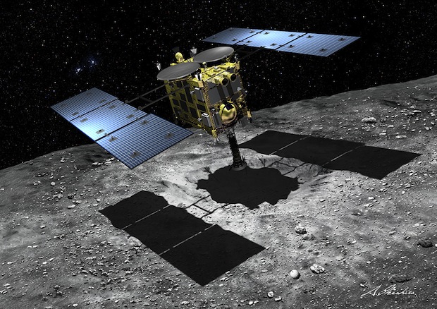
Hayabusa 2


3075201_orig.jpg


Hayabusa 2 is an Asteroid exploration mission by the Japanese Space Exploration Agency setting out to study Asteroid 1999 JU3, dispatch a series of landers and a penetrator, and acquire sample material for return to Earth. The mission builds on the original Hayabusa mission that launched in 2003 and successfully linked up with asteroid Itokawa in 2005 and returned samples to Earth in 2010 marking the first time sample materials from an asteroid were brought back to Earth.

Hayabusa 2 is planned to complete a mission of six years – launching in December 2014 and traveling through the solar system for three and a half years, arriving at 1999 JU3 in July 2018 to spend 18 months studying the asteroid before making its return to Earth in December 2020.

The Hayabusa 2 spacecraft hosts two remote sensing spectrometers dedicated to studying the energy balance of the asteroid and its surface composition. The primary payload of Hayabusa 2 is a sample collection system that will acquire small amounts of surface samples during brief touchdowns of the main spacecraft on the asteroid's surface using a high-fidelity navigation system that allows the spacecraft to make contact with the surface just long enough to shoot down a projectile that causes an ejection of dust for collection by Hayabusa.


Furthermore, the spacecraft will dispatch four landers – the 10-Kilogram MASCOT lander built in Europe for an in-situ study of surface composition and properties, and three MINERVA landers to deliver imagery and temperature measurements. All landers will make several hops across the asteroid’s surface to take measurements at different locations.

Another payload of the mission is an impactor device that will be deployed towards the asteroid and uses high-explosives to generate a high-speed impact that is hoped to expose material from under the asteroid’s surface for later collection by Hayabusa 2. A deployable camera will be used to document the impact of the penetrator.

After all these ambitious events at the asteroid, Hayabusa 2 will make its way back to Earth to send a Return Capsule on its way to re-enter the atmosphere and bring the collected samples back to Earth for analysis.

Hayabusa 1

Launched on an M-V rocket on May 9, 2003, the 510-Kilogram Hayabusa craft embarked on a long flight to its target which had to be changed multiple times due to delays related to the M-V launch vehicle. One year after launch, Hayabusa swung past Earth to accelerate and make its way out to Itokawa in its 0.95 by 1.7 AU orbit around the sun.

The craft officially arrived at its destination on September 12, 2005 when it reached a distance of 20 Kilometers to the asteroid. In subsequent weeks, the spacecraft descended to 7 and then to 3 Kilometers before beginning a descent to deliver a target marker to test out the vehicle's tracking capabilities. This rehearsal landing was aborted due to problems with the optical navigation system and teams needed to re-group ahead of commanding the vehicle to once again descent from 7.5 Kilometers on November 2.

This second descent was a success and saw the spacecraft reaching 70 meters, verifying the navigation system and delivering a landing marker to validate the vehicle’s target tracking capability. With a landing site selected, the spacecraft approached to 55 meters by November 12 when the small MINERVA lander was released, but failed to reach the surface due to an error in its delivery. On November 19, Hayabusa landed on the asteroid, but teams on the ground were confused since the landing came during a handover of ground stations and by the time communications were regained, the vehicle had moved to 100 Kilometers from the asteroid.

It was later confirmed that the vehicle did make contact with the surface of the asteroid, however, a problem during descent put the craft into safe mode so that the sampling system was not activated at touchdown. Nevertheless, the landing was thought to have delivered some dust particles to the sample container that was subsequently sealed off. On November 25, Hayabusa made its second landing, but again failed to initiate its sampling sequence before having to go into safe mode due to a leak in the propellant system.

Over the next two weeks, teams were fighting to keep the mission alive since the spacecraft was loosing attitude control – its reaction wheels had already failed and the thruster leak caused the vehicle to spin – pointing its solar arrays away from the sun leading to power issues and pointing the communication antennas away from Earth. After attempts to correct the attitude by venting xenon gas through the ion thruster system, contact with the probe was lost on December 8 due to a sudden change in orientation. To stabilize, Hayabusa needed time for the conversion of precession rate to pure rotation which was expected to take several weeks.

Finally, on January 23, 2006, beacon signals from the spacecraft were received and three days later, command capability was restored, allowing teams to instruct the craft to make another xenon ejection which improved the orientation of the craft that re-acquired low-gain communications in late February. By March, medium-gain comm had been re-established and tracking showed the craft 13,000 Kilometers from Itokawa. With two out of four ion engines still up and running and 7 of 11 batteries still being recharged, the spacecraft started its return journey in April 2007.

To get back to Earth, the spacecraft completed two several-month long trajectory maneuvers in 2007 and 2009 into 2010. By March 2010, Hayabusa entered its final trajectory adjustment maneuvers to set up a proper re-entry path for the return capsule which required three trajectory corrections, each several days in duration. By June 5, the spacecraft had achieved a re-entry trajectory over the Woomera Prohibited Area in Australia – a broad strip of uninhabited land suitable for the parachute-assisted landing of the return capsule holding the sample containers.

8791963.jpg


Three hours prior to entry, the capsule was released from the spacecraft, on a path to hit the atmosphere at 12.2 Kilometers per second. The return capsule made a successful landing while the main spacecraft burned up in the atmosphere. Several hours after landing, the return vehicle was located and recovered to be flown back to Japan to mark the start of the several-month process of opening the sealed sample containers and extracting any particles.

In November 2010, it was announced that about 1,500 particles of extraterrestrial material were found and in the process of being analyzed. It was determined that the composition of Itokawa was similar to that of rocky meteoroids found on Earth confirming its identity as S-type asteroid. Scientists also determined that the dust collected by the spacecraft was exposed to the space environment for about 8 million years, an extremely short time scale in astronomy. This indicated that Itokawa possibly broke apart from a parent asteroid.


Road to Hayabusa 2

With Hayabusa 1 still on its way through the solar system, a possible follow-on mission was proposed in 2006 to closely resemble the original mission featuring a nearly identical spacecraft with only minor changes to respond to issues seen during the Hayabusa mission. With the initial drive to fly the mission as soon as possible teams were hoping to launch in 2010 or 2011, but the budget did not permit a launch then. The additional development time allowed more changes to be made to the original spacecraft design to use more advanced and robust systems and modify the payload suite, also acquiring international support from NASA and a team of the German Aerospace Center and CNES. New systems were added including a Ka-Band antenna and impactor.

In 2012, the project transitioned from a proposal to a development stage when the Critical Design Review green-lighted the assembly of the spacecraft. Integration tests started in 2013 and the spacecraft was fully integrated by the end of that year, on the road to launch in late 2014.

Target Asteroid

Asteroid 1999 JU3 was discovered by the Lincoln Near-Earth Asteroid Research (LINEAR) that has been heavily studied using ground and space-based telescopes. Telescopic data shows that the asteroid is about 920 meters in size and has a rotation period of 7.6 hours. Spectroscopic analysis showed that that asteroid belongs to the C-type class of primitive bodies. Data also suggests that the asteroid, at some point in its life, was in contact with water. JU3 orbits the sun in an orbit of 0.963 by 1.416 Astronomical units, inclined 5.88 degrees. This orbit, stretching from Earth’s orbit out to just outside the orbit of Mars with a small inclination makes the object suitable for a return mission.

Why Asteroids?

Asteroids, like comets, are of particular interest to scientists since they are primitive bodies that can be considered to be the building blocks of the early solar system and hold a record of the birth and initial evolution of the solar system. Larger planets like Earth went through a more complex evolution over which the pristine materials were melted and altered significantly. Due to this change, the materials found on large planets do not hold information into their early stages of formation.

Comets and asteroids, formed early in the evolution of the Solar System, retain a record of when, where and in what conditions they were formed. Exploration of these primitive bodies is essential in gaining insight into the formation of the Solar System. This may also provide clues into the presence and composition of organic molecules in the early solar system and possible mechanisms of their delivery to Earth. Learning about the formation of our own Solar System will also provide valuable information on exoplanets and their formation.

Asteroids can be divided into different classes based on their composition with each group showing different distributions within the asteroid belt between the orbit of Mars and Jupiter, depending on their distance to the sun. While Hayabusa studied and returned sample from an S-type asteroid that are stony in composition, the follow-on mission will explore a C-type asteroid.
S-type asteroids deliver information on the components of rocky planets such as Mars and Earth; they are also the origin of the LL Chondrite, the most common meteoroid found on Earth. The C-type asteroids are believed to hold a significant amount of organics or hydrated minerals and may have played a role in the delivery of organics to Earth. All this information is based on spectroscopic data from telescopic observations as well as analysis of meteoroids found on Earth.

Other asteroid types that can be found farther from the sun are P- and D-type asteroids that are not abundantly found on Earth due to their stable orbits in the outer region of the asteroid belt or as Jovian Trojans. It is desired that a possible Hayabusa 2 follow-on mission would study one of these types of bodies to get a full picture of the composition of the different primitive bodies.

Hayabusa 2 Spacecraft


2311622.jpg


The Hayabusa 2 spacecraft is similar in architecture to the first Hayabusa spacecraft with a number of notable changes, not only to the instrument and payload suite, but also to the spacecraft platform itself. These changes include the addition of a reaction wheel to create a redundant configuration, the addition of a Ka-Band communications system and changes to the Ion Engine System using more robust technology. Components kept from the original mission allow teams to rely on flight-proven technology that has shown to perform well over the course of a mission lasting over half a decade.

The Hayabusa 2 spacecraft consists of a spacecraft platform 1.6 by 1.0 by 1.2 meters in size using composite materials and aluminum alloy for a structural framework and internal and external panels providing mounting surfaces for the various spacecraft systems and payloads. The vehicle has a dry mass of 490 Kilograms and is capable of holding nearly 100 Kilograms of propellants. With its solar arrays deployed, Hayabusa 2 has a span of six meters.

Electrical & Thermal Systems

2240617_orig.jpg


Power generation is provided by two deployable solar arrays, each consisting of three square panels suspended on two booms that interface with the center panel and the upper deck of the spacecraft platform. With a total surface area of 12 square meters, the arrays are expected to deliver 2,600 Watts of electrical power when the spacecraft is 1 Astronomical Unit from the sun, decreasing to about 1,400 Watts when the vehicle is at 1.4 AU, the aphelion distance of the asteroid. Power is stored in a 13.2 Amp-hour Lithium Ion Battery. Power is distributed to the various satellite systems using a 50-Volt power bus with power being distributed by Series Switching Regulators that provide battery control and bus protection.

The spacecraft includes a cold re-start feature. In the event of a loss of all power, the vehicle can automatically re-start once power generation resumes in order to protect for a loss on sun-pointing attitude or other unforeseen events that can lead to a spacecraft shutdown.

Spacecraft thermal control is accomplished using a combination of passive thermal control featuring blankets and multilayer insulation and active thermal control using thermally conductive coldplate assemblies, heat pipes and radiators installed on the cold side of the spacecraft. Heaters are used to maintain operating temperatures of electronics equipment when needed.

Attitude Determination & Control


9797153_orig.jpg


Hayabusa 2 uses a number of Attitude Determination and Control Systems and a combination of electrical and chemical propulsion. Attitude Determination is provided by two star trackers, two Inertial Measurement Units, four accelerometers and four Coarse Sun Sensors. The Attitude and Orbit Control Unit serves as the brains of the various sensors and actuators – being capable of autonomously maintaining a pre-programmed distance to the asteroid using data from the navigation sensors that also include optical systems and it also controls all descent events to ensure a soft landing and successful ascent. The system uses an extended Kalman filter that outputs the position and relative velocity that are processed using an orbit dynamics tool and a basic gravity field model of the asteroid. The primary attitude sensors are two star trackers which acquire imagery of the sky that is analyzed by a software algorithm that compares the acquired star pattern with a catalog to precisely determine the spacecraft's orientation in space.


Each star tracker has a field of view of around 8 x 8 degrees and uses a CCD detector operating at 1Hz. Hayabusa 2 maintains its attitude through the use of four reaction wheels that allow control of the vehicle about all three axes. The reaction wheel assembly is a rotating inertial mass that is driven by a brushless DC motor that spins the wheel. When accelerating the wheel, the satellite body to which the wheels are directly attached will rotate to the opposite direction as a result of the introduced counter torque.The original Hayabusa spacecraft had only three reaction wheels that were also capable of controlling the orientation on all axes, but did not have any redundancy. Early in the mission, one of the wheels failed followed by another later in the flight, requiring Hayabusa to rely on its engines to maintain its attitude. The addition of a fourth wheel ensures that the system can tolerate the failure of one of the wheels without losing any attitude

The four Coarse Sun Sensors are installed on different sides of the spacecraft and are capable of detecting the direction of the solar vector with some accuracy in order to be able to point the solar arrays to the sun in case of a spacecraft safe mode.

Two redundant Inertial Reference Units are used to augment attitude determination and for use to measure body rates in order to stabilize the spacecraft rates so that the star trackers can acquire star patterns which requires the spacecraft to dampen body rates to a certain level. The accelerometers provide insight into the operation of the propulsion system, allowing the precise tracking of the achieved changes in velocity supplied by the Ion Engine System that will be in operation for several thousand hours over the course of the six year mission.

Propulsion Systems

Like its predecessor, Hayabusa 2 combines a chemical and electrical propulsion system. The spacecraft hosts a bi-propellant chemical propulsion system using Monomethylhydrazine fuel and Nitrogen Tetroxide oxidizer, stored in propellant tanks that are pressurized with high-pressure gas to operate a total of 12 pressure-fed thrusters.

The 12 engines are operated as part of two strings that can be isolated in case of leaks or other problems. The ISAS-20N thrusters deliver a nominal thrust of 20 Newtons at a specific impulse of 290 seconds featuring a film-coating for thruster cooling.

The engines are capable of operating in pulse mode for spacecraft attitude control and in steady-state mode for Cruise Maneuvers and other translational burns. The thrusters also provide de-saturation of the reaction wheels – spinning the wheels down while countering the resulting force with the engines.

Hayabusa 2 will achieve the vast majority of the required change in velocity to travel to and from the asteroid by using its Ion Engine System – IES. Ion thrusters generate thrust by accelerating ions through the use of an electric field and ejecting these ions at extremely high velocity creating thrust force propelling the spacecraft forward. Although ion thrusters deliver a very low thrust, they are extremely efficient and consume only a very small amount of propellant. Through long operation of the thrusters, spacecraft can achieve changes in velocity of several Kilometers per second as demonstrated by Hayabusa 1 (over 2km/s), Deep Space 1 (4.3km/s), and Dawn (over 10km/s).

Ion thrusters use ions to create thrust in accordance with momentum conservation. The method of ion acceleration varies between the use of Coulomb and Lorentz force, but all designs take advantage of the charge/mass ratio of the ions to create very high velocities with very small potential differences which leads to a reduction of reaction mass that is required but also increases the amount of specific power compared to chemical propulsion.

The thrusters operate by releasing small amounts of Xenon atoms that are then ionized through electron bombardment by using electron cyclotron resonance microwave discharge – a new design that eliminated solid electrodes and associated heaters that were used as part of previous systems. The same microwave generator is used to feed the ion generator and neutralizer which reduces overall mass of the assembly. The neutralizer emits electrons near the exiting ion beam to ensure that equal amounts of positive and negative charge are expelled, thus preventing the spacecraft from gaining an excessive electrical charge that could damage components.

The generated ions are extracted by a dedicated system consisting of electrically charged carbon-carbon grids with primary acceleration of the ions taking place between the first and second acceleration grids. The negative voltage of the accelerator prevents ions from the beam plasma outside the thrusters from streaming back which would decrease the generated thrust. The ejected ions push the spacecraft in the opposite direction according to Newton’s third law.

Hayabusa 2 uses four ion thrusters installed on a single panel of the spacecraft, facing the same direction to be able to combine thrust. Three units are in simultaneous operation, allowing the fourth system to come into play in the event one of the active thrusters fails.

The system is fed from a 51-liter xenon tank that can hold about 73 Kilograms of the gas. Each of the thrusters generates an operational thrust of nearly 10 mN at a specific impulse of 2,800 seconds. During operation, the system needs 250 to 1,200 Watts of electrical power. The entire Ion Thruster Assembly weighs about 70 Kilogram and the thrusters can be gimbaled by +/-5 degrees using an electromechanical system.

Improvements made to the propulsion system from Hayabusa 1 to 2 include a 25% increase in thrust and added mechanisms to prevent plasma ignition malfunctions in the ion source. The neutralizer, that had shown degradation after the first 10,000 hours of operation, was improved by protecting the outer walls from plasma and by strengthening the magnetic field to decrease the applied voltage needed for the emission of electrons. Hayabusa 2’s ion thrusters are planned to operate for over 18,000 hours.

389995.jpg


Data Handling & Communications

The Hayabusa 2 spacecraft is controlled by a Central Data Handling Unit that interfaces with all spacecraft systems and is capable of auto-commanding spacecraft functions, execute commands sent from Earth, handle all payload and systems data, and deliver housekeeping and stored instrument data to the communications system of the spacecraft. The Data Handling Unit is based on a COSMO 16 Central Processing Unit and is connected to the Peripheral Interface Modules of the various spacecraft systems using a high-speed data bus. Collected data is stored in a 1GB data recorder.

X- and Ka-Band Antenna

The communications subsystem of the Hayabusa 2 spacecraft is similar to that of Hayabusa 1 with the notable addition of a second High Gain Antenna as part of a Ka-Band communications system. Originally, Hayabusa flew with a large parabolic X-Band High Gain Antenna that took up most of the space on the upper deck of the spacecraft. Improvements in communication technology allows Hayabusa 2 to use two planar High Gain Antennas that are considerably smaller and have a lower mass while maintaining the same capabilities and communications characteristics. Having two high gain communication systems adds redundancy and also expands the vehicle’s overall capabilities in terms of downlink volume. The X-Band system will be used for day-to-day operations, that is, telemetry downlink and command uplink to the spacecraft. The Ka-Band system is primarily used for the downlink of science data, taking advantage of its higher downlink rate of 32kbit/s. The Ka-Band system also allows for a more precise DDOR (Delta-Differential One-way Ranging) that will complement the normal line-of-sight ranging and doppler measurements for improved navigation during the mission.

The two High-Gain Antennas have a very narrow boresight, requiring the spacecraft to point to Earth to enable communications at up to 32kbit/s. A single two-axis gimbaled X-Band Medium Gain Antenna with an 18-degree cone is used for telemetry downlink and command uplink at lower data rates up to 256bit/s when the HGAs are not pointing to Earth. In case the HGA and MGA can not see Earth, Hayabusa 2 will rely on three omni-directional Low Gain Antennas that provide beacon signal and basic telemetry and command uplink capability at 8bit/s.

2095613_orig.jpg


Optical Navigation Systems

In addition to its absolute navigation instruments, Hayabusa 2 includes three Optical Navigation Cameras, a LIDAR, five Target Markers and a Flash Lamp to be used during proximity operations at the asteroid, the release of the landers and rover and the descent and touchdown of the main spacecraft.The three Optical Navigation Cameras are known as ONC-W1 and W2 (Wide-angle cameras) and ONC-T (telescopic camera). The ONC-W1 and ONC-T cameras reside on the nadir-facing panel of the spacecraft, looking straight down at the surface, while the W2 camera is installed on the –x panel to provide a slant view. All three cameras use two-dimensional CCD detectors, 1024 by 1024 pixels in size with pixel sizes of 12 micrometers. The detectors are sensitive in a wavelength range between 350 and 1,060 nanometers, covering the visible and near-infrared wavelengths. The cameras use a common electronics unit that employs a RISC processor and gate-array image processing technology providing image compression, center-finding, bright object detection, correlation tracking, terrain extraction and others needed for optical navigation.The wide-angle cameras each have a field of view of 54 by 54 degrees achieving a resolution of 7 meters per pixel at a distance of 7 Kilometers to the asteroid. ONC-T has a narrow field of view of 5.8 by 5.7 degrees with a ground resolution of one meter from a distance of 7 Kilometers. The telescopic camera has a focal length of 121 millimeters and an aperture diameter of 15 millimeters. It includes a filter wheel containing a magnifying lens, six medium-band band filters with a bandpass of 15 nanometers at 390, 480, 550, 700, 860 and 950 nm, and a single sodium narrow band filter at 590nm with a 10nm bandpass. It takes 4.7 seconds to rotate the wheel from filter to filter. Using its different filters, ONC-T will be used for multi-band spectroscopy. ONC-T will support exposure times of 5.44 milliseconds to 178 seconds with an additional <1 microsecond exposure for streak elimination.The cameras will be used during the cruise phase to acquire imagery of bright stars as well as the Earth Moon system for camera calibration.

ONC Camera Placement on Spacecraft


Even at a large distance, the cameras will already be used to monitor the target asteroid for light curve and spectral observation and searching for a possible satellite of 1999 JU3. At the Home Point of 20km, the cameras are used for imaging the entire surface at a resolution of 2m/pixel using ONC-T that will also yield global spectroscopic observations. In the low-altitude phase, observations will be performed from 5, 1 and 0.1 Kilometers for detailed surveying of local areas in order to find suitable landing sites and a good location for the deployment of the impactor. During lander deployments, the W2 camera will take images of the departing vehicle followed by W1 for descent and trajectory monitoring. After landing, the small vehicles will be located with ONC-T from one Kilometer in altitude.

ONC-T & Bandpass Filters

During the descent for touchdown, the ONC cameras will be the primary navigation instrument from altitudes between 50 and 5 meters.Imagery acquired by ONC will be used for morphological studies of the asteroid, the determination of asteroid volume for bulk density estimation, crater distribution to assess the age of the asteroid and to identify fresh soil locations, and studies of the artificially generated crater. Spectroscopic analysis involving ONC-T will provide information on the spectroscopic characteristics of the different surface features. This analysis will deliver data on basic composition of the surface, degree of hydration of surface materials and the presence of a sodium exosphere that could deliver data on the asteroid’s heating history which is considered an important piece of information by geologists.

LIDAR Laser Source

Hayabusa 2 is outfitted with a LIDAR unit that will be used for navigation when the craft is in proximity to the asteroid, scientific studies of the surface, and a technical demonstration for future optical communications systems. The LIDAR unit measures 24 by 24 by 23 centimeters in size and weighs 3.7 Kilograms comprised of a laser source and an optical head with telescope. LIDAR stands for Light Detection and Ranging and uses laser pulses that are reflected off a target to determine that target’s distance from the spacecraft.The system pulses its 1,064nm infrared laser source at an energy of 10mJ per 10 nanosecond pulse, up to one pulse per second. The laser generates a beam with a divergence of 1.7 mrad, creating a footprint on the surface of about 20 meters from the 20-Kilometer home point. The laser light that is reflected by the asteroid is detected by using a Cassegrain telescope with a primary concave mirror and a secondary convex mirror aligned about the optical axis. The aperture of the telescope is 127 millimeters in diameter and the optics focus the light into a silicon-avalanche photodiode through a narrow-band filter only allowing the desired wavelength to reach the detector. All optical components are installed on a stable optical bench. The LIDAR system will operate at a time resolution better than 3.3 nanoseconds allowing the system to determine the vehicle’s range with an accuracy of +/-5 meters from an altitude of 25 Kilometers, although it is expected that the system will acquire 1999 JU3 from a distance of 50 Kilometers. LIDAR data is provided to the spacecraft computer and the Attitude and Propulsion System to allow the spacecraft to autonomously maintain its planned altitude. When reaching 30 meters, a second set of optics will be employed for measurements up to +/-1 meter accuracy. In addition to delivering valuable navigation data, the LIDAR will record the integrated intensity of each pulse as well as the associated received energy which will yield accurate measurements of surface albedo including that of shadowed areas. Furthermore, the system will provide topographical data.
In a Dust-Count Mode, LIDAR will detect the intensity of scattered light caused by dust in the vicinity of the asteroid. The instrument can not detect the abundance of dust particles, but will show the presence of dust over a certain threshold.

To serve as a demonstrator for future deep-space optical communications, LIDAR will be used around the time of the Earth flyby one year into the mission when a laser pulse will be sent from Earth to be received by LIDAR that will immediately return a pulse to the ground station to demonstrate a basic link experiment. The ground station to be used is NICT Koganei, using a 1.2J laser operating at a pulse repetition rate of 10 Hz. Hayabusa's Laser Range Finder comes into play late in the descent phase, consisting of four laser sources canted 30 degrees. It is activated at around 35 meters in altitude to deliver four oblique range measurements that are used by the attitude control system to keep the spacecraft pointed to the local vertical – ensuring that the bottom panel remains aligned with the local surface during the final meters of descent that are driven by the asteroid’s weak gravitational force. A fifth laser range finder is pointed at the sampling horn for the detection of contact signaled by motion of the sampling horn. Hayabusa carries a series of five Target Markers that are released towards a landing site to provide a tracking target for the vehicle’s navigation instruments. These spherical, bean-bag type target markers are installed on the underside of the spacecraft to be released at an altitude of about 40 meters when the craft is approaching its landing site.

4805316.png


After releasing the marker, the spacecraft slows down to allow the marker to fall away from it and make contact well before the spacecraft. Once at an altitude of 17 meters, the spacecraft reduces its velocity to zero and enters a free-falling descent. At that point, the target marker is already on the surface and ready to be used for navigation. During final descent, the Optical Navigation Cameras W1 & T1 on the nadir-facing panel operate a Flash Light that is activated every two seconds and imagery is acquired with the light on and off to allow the onboard software to subtract the two images from one another to determine the position of the target marker. This technique is used to identify any horizontal velocity that has to be eliminated by the spacecraft in order to achieve a safe landing, otherwise an abort would occur. Another optical navigation method is tracking of bright pixel groups to estimate horizontal velocity. A final optical part of the landing navigation system are four Fan Beam Sensors that are installed on the solar panels of the spacecraft. Each side features one transmitter and receiver that create a three-dimensional detection area under the solar panels to detect any obstacles that could endanger the spacecraft during landing which would trigger an automated abort.
 
JAXA - Japan's Space Agency

Orbital Systems

ASNARO-1


ASNARO, the Advanced Satellite with New system ARchitecture for Observation, is a Japanese satellite project developed by NEC Corporation and USEF (Institute for Unmanned Space Experiment Free Flyer) under funding from NEDO (New Energy and Industrial Technology Development Organization). The overall aim of the project is to develop a next-generation small-satellite bus with high-performance characteristics and flexibility to be able to support a number of payloads.

The ASNARO project was initiated in 2008 with the goal of developing a satellite bus with an open-architecture that reduces development and manufacturing cost while utilizing state-of-the-art technologies. ASNARO satellites will be employed in Earth observation missions, capable of supporting optical imagers, hyperspectral payloads and radar instruments. The ASNARO-1 satellite is outfitted with a high-resolution optical imaging instrument that can deliver imagery at a ground resolution of under 0.5 meters in the panchromatic band and under 2 meters for multispectral images.

_7813135.jpg


ChubuSat-1


ChubuSat-1, informally called Kinshachi, is a microsatellite project of Nagoya and Daido Universities and several aerospace companies located in the Chubu region of Japan. The mission demonstrates a cost-effective satellite platform and an imaging payload that will make observations of Earth in visible and infrared wavelengths, track space debris and serve outreach purposes by relaying messages via the amateur radio bands.

The spacecraft utilizes a standardized modular satellite bus that is 58 by 55 by 50 centimeters in size with a launch mass of around 50 Kilograms, designed to operate in orbit for six months to one year. The satellite uses an aluminum skeleton with internal and external honeycomb panels to create a lightweight but stiff structure.

_4967354_orig.jpg


Three of the external panels host triple-junction gallium-arsenide solar cells for a total of 60 cells per panel operated in three strings for a total power output of 100 Watts. Control of the power system is provided by a Power Control Unit which delivers generated power to a NiMH battery that consists of five strings with a total capacity of 9.5 Amp-hours. The PCU also conditions the satellite's power bus at 28 Volts with an operational range of 23 to 36 Volts - from this non-regulated bus, the PCU generates voltages of 5, 12 and 15V for use by the various electronics. The PCU controls the state of charge of the battery, distributes power to all subsystems, shunts power from the solar panels and provides housekeeping data to the onboard computer.

ChubuSat-1 uses passive thermal control in form of blankets and insulation in combination with heaters that are used to maintain an operational thermal environment for the main components of the satellite.

The spacecraft is three-axis stabilized using reaction wheels and magnetic torque rods. Navigation sensors employed by the satellite is one Star Tracker, three sun sensors, a three-axis magnetometer, and three Fiber-Optic Gyros to measure body rates.
The spacecraft is controlled in a two-axis stabilization mode using only the torque rods during safe mode and initial de-tumble/attitude acquisition with an attitude error of under five degrees. Three-axis control is accomplished through the reaction wheels with a pointing accuracy better than 0.8 degrees. Regular momentum dumps from the reaction wheels are done by de-spinning the wheels and countering the resulting torque using the magnetic rods.

The data system of the satellite uses SpaceWire interfaces to connect the various controllers to the Onboard Computer which consists of three modules - a Central Processing Unit, an interface unit and a power supply. The OBC is 27 by 21 by 13 centimeters in size weighing 5 Kilograms including Attitude and Orbital Control Units, the Data Handling Unit interfacing with the payload, the main Data Recorder and the Command Decoder that interfaces with the communications systems.

_2242034_orig.jpg


The onboard computer provides self-check capability, regularly clears a watchdog timer, controls the satellite time, calculates the vehicle's attitude and commands attitude actuators, processes housekeeping and payload data, provides failure detection and isolation and it also provides reprogramming capability.
The 32-bit central processing unit operates at 50 MIPS and includes 1 MB of EEPROM containing the boot code, 2 MB of SRAM, 64 MB of SDRAM and 512 MB of Flush ROM.

ChubuSat-1 uses a communications system operating at the amateur VHF/UHF frequencies reaching a data rate of 1.2 kbit/s for uplink and 9.6kbit/s for downlink. The comm system uses two amateur radio transceivers, a transmitter switch and a set of two receiving and two transmitting antennas. The receiving antennas are held in their launch position folded against the satellite body by a nylon wire that has a niochrome wire wound around it. Once separated in orbit, the PCU applies power to the niochrome wire that heats up and cuts the nylon wire to free the antennas that then spring into a deployed position.

ChubuSat-1 carries two instruments - a visible-near infrared imager and a dedicated infrared imaging payload. The Visible Camera covers a spectral range of 400 to 800 nanometers to create full-color imagery using a CMOS detector of 2048 by 1536 pixels with a 3.5-micrometer pixel size. The imager has a narrow field of view of 2.15 by 1.61 degrees and achieves a ground resolution of ten meters. Built-into the payload is a 2 GB flash memory that stores acquired data.

The optical head of the camera is 18 by 7.5 by 7.5 centimeters in size and connected to an electronics box. Overall, the instrument weighs just under one Kilogram.

The Thermal Infrared Camera covers a spectral range of 7.5 to 13.5 micrometers using a bolometer array. The Bolometer Array Instrument is an uncooled infrared imager that does not rely on a cryocooler to keep the detector cooled. The array consists of 320 by 240 pixels. Each pixel on the array consists of several layers including an infrared absorbing material and a reflector underneath it that directs IR radiation that passes through the absorber back to the absorbing layer to ensure a near complete absorption. As IR radiation strikes the detector, the absorbing material is heated and changes its electrical resistance which can be measured via electrodes connected to each microbolometer and processed into an intensity read-out.

The TIR camera achieves a spatial resolution of 130 meters. Overall, the instrument weighs just 500 grams and is 8 x 8 x 15 centimeters in size. The TIR camera will be used to measure Earth surface temperature and to look for thermal signatures of orbital debris.

Hodoyoshi-1

Hodoyoshi-1 is a microsatellite developed by AxelSpace and the University of Tokyo. It is the third Hodoyoshi satellite to launch following in the footsteps of Hodoyoshi 3 and 4 that launched earlier in 2014.
The project aims to change the development of satellites to introduce cost-effective systems that can be used in a variety of applications with one primary focus being Earth-observations using miniaturized optical payloads. Hodoyoshi can be translated as "Reasonably Reliable Systems."

_7054932.jpg


The Hodoyoshi-1 satellite is 50.3 by 52.4 by 52.4 centimeters in size using an aluminum structure with internal and external panels. The satellite weighs 60 Kilograms and is equipped with body mounted solar cells that deliver around 50 Watts of electrical power that is distributed using a 28V and a 5V power bus. Power is stored in a Li-Ion battery.

The satellite is three-axis stabilized using star trackers, an inertial measurement unit and a reaction wheel assembly to provide very accurate Earth pointing capabilities with an attitude error of under 0.1 degrees. Orbit determination is provided by a GPS sensor. Normally, the satellite will be in a nadir-pointing attitude, facing its camera and antennas toward Earth.

The satellite uses a Field Programmable Gate Array as main processing unit. Telemetry downlink and command uplink is accomplished via an S-Band system with an uplink rate of 4kbps and a downlink rate of 4 to 64kbps. Mission data is downlinked via an X-Band system achieving data rates of up to 20 Mbps. The Hodoyoshi-1 satellite is outfitted with a Hydrogen Peroxide propulsion system for orbital maneuvers and orbit maintenance.

The primary payload of Hodoyoshi-1 is an optical imaging system that uses a pushbroom (line scanning) design employing a refractive telescope and lenses that create a wide field of view to be able to cover a wide ground swath of 27.8 Kilometers when pointing nadir.

_601592_orig.jpg


The imager covers four spectral bands, the conventional RGB bands to create full-color Earth imagery plus a near infrared channel - Blue (450-520nm), Green (520-600nm), Red (630-690nm) and Near-Infrared (780-890nm).

Hodoyoshi-1 will achieve ground resolutions of 6.7 meters, its imagery being used for agriculture monitoring, forestry, fishing, mapping, disaster monitoring and other purposes. The maximum strip-length of imagery acquired by Hodoyoshi is 179 Kilometers.

Tsubame

_3207296_orig.jpg


Tsubame is a microsatellite project of Matunaga LSS (Laboratory for Space System) at the Tokyo Institute of Technology that combines technical and scientific mission objectives. The 50-Kilogram satellite will demonstrate an agile attitude control system based on Control Moment Gyros, acquire Earth imagery and study gamma-ray bursts and X-ray emissions.

Tsubame means 'swift' - a name chosen to reflect on the mission's objective of demonstrating a quick attitude control system and due to parallels with NASA's Swift mission that also studies gamma-rays.

The overall technical goals of the mission are the demonstration of the microsatellite bus that includes Commercial Off The Shelf COTS components, the demonstration of the Control Moment Gyros and the demonstration of a high-resolution optical imager.

Scientific goals identified for this mission are the observation of gamma- and X-ray sources in a responsive system that uses the satellite's high agility to automatically identify and point the instrument to events of interest.
The satellite uses a nearly cubic platform measuring 50 by 50 by 47 centimeters, comprised of a lattice structure and external panels. Four solar panels are deployed once in orbit to face in the same direction and ensure optimal power-generation when in sun-pointing mode. The side panels of the satellite are outfitted with additional solar cells to ensure some power is generated in any spacecraft orientation. Tsubame uses indium-gallium-arsenide solar cells that are grouped in six strings, interfacing with the EPS Board and a 6-cell Lithium-Polymer battery.

The EPS board controls the state of charge of the battery and provides solar array shunting when required. Overall, the solar cells deliver more than 100 Watts of electrical power. Using DC to DC converters, the EPS hardware generates voltages needed by other electronic components of the satellite, conditioned from an unregulated power bus at 25-32 Volts.

_7798000.jpg


Thermal control of the satellite uses multilayer insulation to keep all components in a stable thermal environment. More than 40 temperature sensors are used to keep track of temperatures in various positions of the satellite.

The Attitude Determination and Control System uses CMGs and Magnetic Torquers for attitude actuation and a series of sensors for navigation and attitude control. Each satellite panel is equipped with one sun-sensor to allow a fast determination of the solar direction and point the solar panels at the sun in case of spacecraft safe mode. A three-axis magnetometer and a redundant set of two star trackers are used for precise attitude determination in combination with Fiber Optic Gyros that accurately measure body rates.

The miniature Control Moment Gyroscopes are the primary focus of Tsubame's technical demonstration mission. Four CMGs are installed in a pyramide to be able to provide three-axis stabilization with agile pointing capability. A CMG consists of a spinning rotor and motorized gimbals that can tilt the rotor's angular momentum resulting in a gyroscopic torque acting on the spacecraft, causing it to rotate since the CMGs are firmly installed on the spacecraft structure. CMGs differ from reaction wheels that impart toque by simply changing the speed at which they rotate. Overall, CMGs require less energy and deliver much higher torque than reaction wheels which are simpler in design and for most spacecraft are the best solution.

Each CMG used on Tsubame is 7.35 centimeters in diameter with a total length per assembly of 15 centimeters and a mass of 1 Kilogram per wheel. The wheel is rotated by a synchronous motor to generate an angular momentum of 0.053 Nms. A step motor is used to gimbal each wheel along one axis with a speed of +/-1.0rad/s while an RV resolver delivers the current gimbal position to the ADCS controller as feedback. Overall, the CMGs used on Tsubame can generate 53mNm of torque for very fast re-orientations of the spacecraft while maintaining a pointing accuracy of 1° and a stability of better than 0.5°/s.

The Tsubame spacecraft uses a central Onboard Computer based on Field Programmable Gate Array technology to control all vehicle functions and sequences, and handle all housekeeping and payload data as well as communication tasks. A Peripheral Interface Controller is used to monitor the OBC health. The OBC interfaces with other systems using a CAN data bus with the exception of the Electrical Power Systems and the Peripheral Interface Controller that use UART links (Universal Asynchronous Receiver/Transmitter).

Communications are done via the amateur VHF/UHF bands for command uplink and housekeeping data downlink while S-Band is used for payload data transmission. The 430MHz UHF downlink channel reaches data rates of 9.6kbit/s while the 144MHz VHF uplink is done at 1.2kbit/s. The S-Band system uses BPSK modulation and reaches downlink data rates of 100kbit/s.

Tsubame is equipped with two payloads - an Optical Camera and a Gamma-Ray Observation System, GROS. The optical camera is used for Earth observations at moderate resolutions for use in landmark tracking, environmental monitoring, and panorama imaging.

The Optical Camera is 9 by 10 by 20 centimeters in size with a total instrument mass of 1 Kilogram and a power demand of 3 Watts or less. A Field Programmable Gate Array is used as an instrument controller, responsible for the operation of all the camera's functions.
The camera has a focal length of 17.5 centimeters and uses a detector of 2,210 by 3,002 pixels that can operate at a read-out speed of up to 5 images per second. The Optical Imager achieves a ground resolution of 14 meters.

GROS, the Gamma Ray Observation System consists of two main components - the Wide Field Burst Monitor (WBM) and the Hard X-Ray Compton Polarimeter (HXCP). WBM is in charge of the detection of Gamma-Ray Burst Events (GRBs) and determine their direction so that HXCP can be pointed to the event location for observation taking advantage of the satellite's high agility provided by the Control Moment Gyros, pointing the satellite to the proper viewing direction for HXCP within 15 seconds.

The Wide Field Burst Monitor consists of five separate units that point to different directions. WBMs are flat plate CsI scintillators 6 by 6 centimeters in size and 0.5 centimeters in depth. Continuous count rates of the WBMs are received by the Main Processing Unit. When an increase in count rates is sensed, basic centoid calculations can be made to determine the direction of the event by using data provided by all five sensors. The calculation is done with an accuracy of +/-10° which is sufficient to then position the satellite for event viewing by the HXCP instrument. The re-orientation is completed within 15 seconds from the event trigger.

Each WBM weighs 260 grams and has a minimum energy threshold of 30keV and a minimum count rate of 10 Hz.

HXCP, the Hard X-ray Compton polarimeter aims to analyze the polarization plane of x-rays entering the instrument to yield information on the mechanism of the emission - the distribution of magnetic field, radiation field and matter around the sources which are rotating pulsars, accreting black holes and active galactic nuclei. Polarization analysis has not been performed on a reliable level at different energies and information provided by the instrument is hoped to increase understanding in x-ray and Gamma-ray sources.

The HXCP instrument is pointed to the direction of an even within 15 seconds of the trigger and so can observe the majority of x-ray events that commonly have durations on the order of 40 seconds. HXCP can detect photons at an energy range of 30 to 200 Kilo-Electronvolt utilizing the azimuthal angle anisotropy of Compton scattering.

The instrument consists of a scatterer that is used to determine the incidence angle of incoming X-rays before the photon energies are detected by using an absorber. The scatterer consists of 64 (8 by 8) plastic scintillators (6.5 x 6.5 x 49mm) located in the center of the detector while the absorber uses 28 Cesium Iodide scintillators (6.5 x 10 x 49mm). The scintillator signals are read-out by photomultipliers (Multi-Anode Photo Multiplier Tubes Avalanche Photodiodes).

HXCP has a field of view of +/-15 degrees with an effective detector area of 7cm².

To subtract x-ray background radiation and atmospheric gamma rays, the instrument uses a coincidence technique, rejecting all events that do not strike the scatterer and absorber at the same time. Background rejection is also optimized by the shielding of HXCP consisting of lead, tin and copper.

QSat-EOS

_721984_orig.jpg


QSat-EOS, the Kyushu Satellite for Earth Observation System Demonstration, is a microsatellite developed at Kyushu University in a project initiated in 2005 to demonstrate a small scientific payload for the observation of Earth, the study of Earth's magnetic field, an assessment of micro debris in orbit and water vapor observation in the upper atmosphere. Another task that the satellite will fulfill is the demonstration of a de-orbit sail for space debris mitigation.

The microsatellite is nearly cubical in shape, 49.2 by 50.3 by 50.2 centimeters in size with a total mass of under 50 Kilograms. The satellite consists of aluminum alloy panels that offer internal and external mounting structures for the various satellite systems.

QSat is equipped with a total of 200 body-mounted gallium-arsenide solar cells that deliver an average power of 74 Watts to a Power Unit that distributes power to all satellite subsystems and controls the battery unit which itself consists of 18 Nickel-Metal Hydride AAA batteries six of which are connected in series creating three parallel strings for a total capacity of 10.5Ah. The satellite uses a 7.2-Volt power bus. The Power Unit is also in charge of satellite activation when sensing the activation of the separation switch inside the payload adapter.

A Central Onboard Computer based on an H8/2638 microprocessor is used to control all the satellite's functions, connected to all systems through a CAN bus that interfaces with the various subsystem controllers which themselves are equipped with their own CPU, SRAM memory and EEPROM memory. The OBC supports two CAN channels and two serial connections with a built-in memory of 1MB of SRAM and 2MB of EEPROM containing the boot code.

Attitude determination is accomplished by two star trackers, two sun sensors, a three-axis magnetometer and Fiber-Optic Gyros. Actuation is provided by a Reaction Wheel Assembly and Magnetic Torque Rods. QSat requires a pointing accuracy of better than 5°. A dual GPS antenna is used for orbit determination.

QSat is outfitted with two S-Band patch antennas and a Ku-Band horn antenna for communications. The Ku-Band system consists of separate receiver and transmitter electronics connected to the antenna via a duplexer to support an experimental uplink capability at a data rate of 10Mbit/s and an operational science data downlink at 30Mbit/s. The Ku-Band transmitter is connected directly to the imaging payload via a USB 2.0 connection to enable a direct downlink of high-volume data.

Also using separate transmit and receive systems, the S-Band communications terminal can achieve data rates of 1kbit/s for command uplink and 100kbit/s for housekeeping data downlink.

QSat-EOS carries three instruments: a Two-Band VNIR Imager, a Magnetometer and a Debris Sensor.

The primary objective of the mission is Earth observation for environmental monitoring, resource studies for agriculture and forestry as well as disaster monitoring. The VNIR payload is a staring imager that has an aperture diameter of 10 centimeters and a focal length of 40 centimeters, covering two spectral bands - 525-605nm in the visible range and 774-900nm entering the near-infrared spectral range. The payload has a field of view of 9 by 9 degrees and uses a CMOS camera with a 2000 by 2000-pixel detector to create imagery with a ground resolution better than 5 meters.

The Magnetometer payload is a fluxgate magnetometer for the study of magnetic field variations caused by Field-Aligned Currents in the polar and equatorial regions which are known to cause charging on orbiting spacecraft. The instrument is a commercial magnetometer produced by Honeywell (HMC2003T). The fluxgate sensor uses the nonlinearity of magnetization properties for the high permeability of easily saturated ferromagnetic alloys to serve as an indicator for the local field strength.

Data from the magnetometer will be used for an assessment of Field-Aligned Currents in the polar region and poorly understood FACs in the equatorial region - delivering data that can be compared to measurements made by ground-based Magnetic Data Acquisition Systems.

The Debris Sensor has been design to study micro debris in orbit using an in-situ detector that is capable of measuring debris from a size of 100 microns to several centimeters in order to provide data on the distribution and flux of such debris with focus on size range which can not be determined by ground based assets.

The detector is installed on the -Y Panel of the satellite with a sensing element 10 by 10 centimeters in size. It consists of 0.05-millimeter wide copper wires that are installed on a polyamide film spaced 0.1 millimeters. The current through each line is monitored to detect changes which can point to the occurrence of debris events and the number of affected wires can be used to determine the debris size.

At the end of its mission QSat will deploy a de-orbit sail to demonstrate an accelerated orbital decay for debris mitigation. The sail consists of a deployable boom that has a three-meter long and 35-centimeter wide Kapton film attached for a significant increase in orbital drag.

@Nihonjin1051 - Japan Can Into Space:yahoo::dance3::yay:!!!
 
JAXA -Japan's Space Agency

Orbital System

ALOS-2 - Radar Observation


ALOS-2 - the Advanced Land Observation Satellite 2 is a radar Earth Observation satellite operated by the Japanese Aerospace Exploration Agency to acquire high-resolution radar imagery of Earth for cartography, regional observation, resource management, disaster management and scientific purposes. The satellite is the follow-on project to ALOS-1 that was launched in January 2006 and operated for five years until experiencing a complete power loss in 2011.

ALOS-2 will enhance the capabilities of the previously flown SAR payload on ALOS and provide an increased resolution, faster revisit times, and observation at high incidence angles.

ALOS-2 was manufactured by Mitsubishi Electric Corporation under contract by JAXA to facilitate two primary instruments - the PALSAR-2 Phased Array L-Band Synthetic Aperture Radar, a Compact Infrared Camera - and a small AIS (Automatic Identification System) terminal.

The spacecraft weighs 2,120 Kilograms and is 9.9 by 16.5 by 3.7 meters in size when fully deployed on orbit. ALOS-2 uses a modular approach consisting of a bus module, the large L-Band SAR antenna, a payload electronics unit and two small payload modules for the Compact Infrared Camera and the Space Based Automatic Identification System Experiment 2.

ALOS-2 is equipped with two three-panel solar arrays using triple-junction gallium-arsenide solar cells for a total output power of 5,200 Watts at the end of the mission. A dedicated avionics unit is responsible for the conditioning of the satellite's main power bus and of the regulation of the state of charge of the onboard batteries.

Spacecraft thermal control is accomplished using a combination of passive thermal control featuring blankets and multilayer insulation and active thermal control using thermally conductive coldplate assemblies, heat pipes and radiators installed on the space-facing side of the spacecraft. Heaters are used to maintain operating temperatures of electronics equipment when needed.

Attitude control and actuation is accomplished by a suite of attitude sensors and a combination of thrusters, reaction wheels and magnetic torquers.

4788369_orig.jpg


ALOS-2 is equipped with a Star Tracker Assembly consisting of three optical heads and corresponding analog and digital electronic units building a redundant system.

Two of the star trackers are used at a time to acquire imagery of the sky that is analyzed by a software algorithm that compares the acquired star pattern with a catalog to precisely determine the spacecraft's orientation in space. Each star tracker has a field of view of 8 by 8 degrees and uses a CCD detector operating at 1Hz. Overall, the star tracker assembly weighs 40 Kilograms and has a peak power consumption of 150 Watts.

In addition to its Star Trackers that have a maximum acquisition rate of 0.1 deg/s, ALOS-2 uses an Inertial Reference Unit for three-axis attitude and rate sensing that ensures control at higher rates e.g. during initial attitude acquisition. Additionally, an Earth Sensor and Coarse Sun Sensors are installed on the satellite to ensure good Sun/Earth-pointing in spacecraft safe mode.

Attitude actuation is provided by a propulsive attitude control system featuring a series of 1-Newton Hydrazine monopropellant thrusters as well as a Reaction Wheel Assembly and magnetic torquers that are used in spacecraft safe mode and during RWA momentum dumps. For the operation of the SAR payload, ALOS-2 has to be capable of rapid and accurate attitude maneuvers about its roll axis in order to achieve side-looking of its SAR antenna. Body pointing in roll for SAR observation is possible from +30 to -30 degrees.

To minimize the time required for attitude maneuvers, ALOS-2 employs a specially developed Reaction Wheels Assembly consisting of five wheels. Four wheels are used as a standard Reaction Wheel Assembly that ensures redundancy in three-axis spacecraft pointing. The fifth wheel is aligned with the roll axis to maximize maneuverability for quick roll maneuvers taking 109 seconds from nadir-looking to +/-30 degrees side-looking or 159 seconds for a slew from left to right.

Overall, the Reaction Control Wheels can deliver 0.9Nm of output torque and a maximum momentum of 40 Nms at 3200 rpm with a maximum roll rate of 0.7 degrees per second.

The ALOS-2 mission principle requires a rapid data availability after acquisition and the spacecraft employs a twofold communications architecture with an X-Band system for payload data downlink to the ground and a Ka-Band terminal for data transfer to a data relay satellite in Geostationary Orbit.

ALOS-2 uses a Mission Data Handling System that processes and stores data acquired by the payloads as well as systems telemetry in a 130GB memory ahead of data downlink.

To meet the high data downlink volume requirement, ALOS-2 employs an innovative XMOD System, Multi-mode High Speed Modulator that is capable of achieving a maximum data rate of 800Mbit/s using Quadrature Amplitude Modulation (16QAM) and Quadrature Phase Shift Keying to remain compatible with existing ground stations. The system consists of a baseband module featuring the necessary Serializers&Deserializers, Digital to Analog Converters, a Temperature Compensated Crystal Oscillator and SRAM-based FPGA.

The X-Band carrier is generated by a load oscillator while the RF module is in charge of quadrature modulation on the signals generated by the baseband module followed by signal amplification. ALOS-2 uses two X-Band antenna arrays. The XMOD system has a mass of four Kilograms and fits into an envelope of 30 by 12 by 19 centimeters. It is internally redundant and supports data rates of 200, 400 and 800Mbit/s at frequency bandwidths of 240 and 123 MHz.


221584_orig.jpg


On the space-facing deck of the spacecraft resides the gimbaled Ka-Band antenna of the satellite that is used to transmit data to the Kodama Data Relay Test Satellite using QPSK Modulation at a data rate of up to 277 Mbit/s.

Ka-Band Antenna

8745043_orig.jpg


For its precise orbit control scheme, ALOS-2 is equipped with a Spaceborne GPS receiver that provides precise orbit data to the vehicle for orbit monitoring and maneuver planning. The dual-frequency GPS receiver uses both, signals in the L1 and L2 bands, however, the L-Band radar frequency used by ALOS-2 overlaps with the L2 navigation signal - requiring the L2 input to be switched off during SAR observations.

The requirement of an orbit determination accurate to ten meters is far surpassed by the GPS receiver installed on ALOS-2 achieving accurate measurements of 0.5 to 0.8 meters in L2 Loss Mode and better than 0.2 meters using L1 and L2 signals.

ALOS-2 operates in a Near-Circular Sub-Recurrent Sun-Synchronous Orbit at an altitude of 628 Kilometers and an inclination of 97.4 degrees creating a revisit time of 14 days. The mission includes a strict orbit maintenance scheme to ensure a high coherence of interferometry measurements. Therefore, the ALOS-2 satellite has to be kept within a 500-meter tube around a precisely calculated reference orbit.

Precise GPS measurements, detailed perturbation modeling and repeat cycle modeling are employed for orbit determination, prediction and orbit maintenance maneuver design. To keep ALOS-2 within its orbital corridor, an average of one in-plane maneuver every five days for drag-makeup and one out of plane burn every 176 days will be needed with in-plane burns as frequent as every 1.5 days during periods of high solar activity.

Because of the high maneuver frequency, ALOS-2 uses an autonomous orbit maintenance system that coordinates maneuvers autonomously without the need of maneuver command design on the ground. Mission planners will allocate several maneuver slots per day in accordance with planned SAR observations to prevent orbit maintenance from impacting satellite operations.

From these orbital maneuver slots, the autonomous system then chooses a slot when a maneuver is required - as calculated by using GPS parameters for orbit determination and the reference mean element data for orbit error calculation. Once a slot is selected, the system automatically computes the required delta-v, time of ignition and spacecraft attitude before developing maneuver commands ready for execution by the spacecraft.

A number of safeguards within the software and the ALOS control system and attitude control system software prevent erroneous burns of long duration that would put the satellite in an incorrect orbit.


PALSAR Payload

The main instrument of the ALOS-2 spacecraft is PALSAR-2 - the Phased Array L-Band Synthetic Aperture Radar-2 that uses Active Phased Array Antenna technology. Radar satellites bounce radar signals off the ground and record the weak echo signal to deduce radar reflectiveness of sites on the ground which differs between the various types of vegetation, water bodies and man-made structures. Overall, the system consists of two main components: the antenna subsystem and the electric unit. The antenna is 2.9 meters wide and 9.9 meters long weighing 548 Kilograms.

The PALSAR-2 instrument supports observations in stripmap mode as well as spotlight and ScanSAR modes to achieve a ground resolution of one to three meters. Beam steering in range and azimuth and side-looking observations and a coverage of wide incidence angles of 8 to 70° allows the instrument to cover a wide area on the ground of up to 2,320 Kilometers to support high revisit times.

The SAR antenna consists of five panels featuring a total of 1,080 active radiation elements driven by 180 Transmit and Receive Modules (TRM) that provide the transmit signal and process the received signal. When operating at full power, the SAR power requires 5,100 Watts of power, but the payload can also be operated in a partial-aperture mode that only uses panels 2,3 and 4 requiring 3,300W of power.

The radar signals transmitted and received by the antenna are conditioned and processed in the electric unit that consists of an exciter, transmitter, receiver, digital processor and systems controller. The exciter generates the chirp signals that are then up / down-modulated. The radar has a selectable center frequency of 1236.5, 1257.5 or 1278.5 MHz that can be stretched to bandwidths of 84, 42, 28 or 14 MHz. PALSAR operates at Pulse Repetition Frequencies of 1500 to 3000 Hz and supports different polarization modes.

The Transmit Receive Modules provide Tx and Rx gain and phase control. The systems can support rapid beam steering, beam shaping and polarization selection - it is a dual-polarized antenna that can transmit in a selected polarization and receive in both polarizations simultaneously. A Compact Polarimetry Mode allows simultaneous transmission of H and V polarization to achieve a linear polarization.

Each TRM weighs about 0.4kg and measures 20 by 11 by 1.5 centimeters in size. The system features High Power Amplifiers using Gallium Nitride High Electron Mobility Transistors to provide an output with low-loss and high-power characteristics achieving an output power of 34 Watts at an efficiency of 35%.

In receiving mode, the weak echo signal is amplified by Low Noise Amplifiers in the electronics and summed up using the same network as the transmit system. After filtering, the receive signal is digitized, formatted and recorded. Signal compression is accomplished via Block Adaptive Quantization using a compression up to 4-bit.


TRM Design


9807923_orig.jpg


PALSAR is capable of operating in three different modes - the conventional stripmap mode, spotlight mode and ScanSAR Operation. In stripmap mode, the payload can be operated on an ultra-fine, a high-sensitivity and in fine mode to achieve different resolutions and ground swath widths.

In the fine stripmap mode, PALSAR covers a 70-Kilometer ground swath operating at one of its three selectable frequencies and a bandwidth of 28MHz. Fine stripmap achieves a ground resolution of 10 meters providing a data volume of 400Mbit/s. In this mode of operation, the instrument supports single polarization, dual polarization, full polarization (quad polarization) and the experimental Compact Polarization.

The High Sensitivity mode also supports these different polarization modes and all three frequencies, but operates the radar at a bandwidth of 42MHz covering a 50-Kilometer swath with a maximum ground resolution of 6 meters creating a data volume of 800Mbit/s.

In the ultra-fine stripmap mode, PALSAR can only operate in single and dual polarization mode and only supports its center frequency of 1257.5 MHz. Covering a 50-Kilometer swath and operating at a bandwidth of 84MHz, the ultra-fine mode reaches ground resolutions of 3 meters.

The spotlight mode uses single-polarization imaging of ground tiles of 25 by 25 Kilometers operating the radar at the center frequency o 1257.5 MHz and a bandwidth of 84MHz. This high-resolution mode achieves a ground resolution of 3 meters in range and 1 meter in azimuth.

ScanSAR allows the instrument to cover a wide swath of 350 Kilometers with a resolution of 100 meters in single and dual polarization mode, and a selectable frequency. Operated in this mode, PALSAR operates at 14 MHz and delivers a data volume of 400Mbit/s.

The Full Polarization mode switches between horizontal and vertical polarizations at the Pulse Repetition Interval which doubles the time of repeat pulses and reduces the available swath from 70 to 30 Kilometers.
Calibration of the SAR payload is accomplished using internal calibration to track the performance of the radar over time and compare it to pre-flight calibrations. External calibration uses ground targets of known properties to provide and end-to-end calibration of the system.

Compact Infrared Camera

The Compact Infrared Camera CIRC is a small payload developed by MELCO under contract from JAXA using COTS (Commercial off the Shelf) components to build a compact infrared imager for deployment on several spacecraft to create an operational wildfire detection capability. CIRC is making its first flight on ALOS-2 and will also be deployed on the International Space Station.

490487_orig.jpg


CIRC weighs just under 3 Kilograms and is 18 by 11 by 23 centimeters in size. Because of its compact size, low power consumption and low data rates, the instrument is ideal for deployment as secondary payload on a number of spacecraft.

The infrared imager has an aperture diameter of 6.5 and a focal length of 7.8 centimeters and uses athermal optics to avoid defocus caused by temperature changes of the optics using a chalcogenide glass and a series of germanium lenses and windows. The instrument has an operational range of -15 to +50°.

CIRC uses a shutterless design approach to simplify and downsize the instrument, however, this eliminated a calibration source as a closed shutter can be used for instrument calibration. Instead, stray light correction is accomplished as a function of instrument temperature measured by a sensor and complementing ground testing using black body imaging.

To comply with its low power and small size requirements, CIRC could not be outfitted with a cooling system that is usually employed for infrared detectors. Therefore, microbolometer array that does not require cooling was selected as detector. Each pixel on the array consists of several layers including an infrared absorbing material and a reflector underneath it that directs IR radiation that passes through the absorber back to the absorbing layer to ensure a near complete absorption. As IR radiation strikes the detector, the absorbing material is heated and changes its electrical resistance which can be measured via electrodes connected to each microbolometer and processed into an intensity read-out.

CIRC uses a Silicon-On-Insulator SOI diode Focal Plane Array with a size of 640 by 480 pixels and pixel sizes of 25 micrometers. The detector has low-noise characteristics and a high sensitivity in the spectral range of 8-12 micrometers. The instrument has a field of view of 12 by 9 degrees and a dynamic range of 180 to 400K. The nominal exposure time is set at 33 milliseconds.

At an altitude of 600 Kilometers, the instrument achieves a spatial resolution of 200 meters which is sufficient for the detection and monitoring of wildfires, the observation of volcanoes and the assessment of 'hot spots' created by cities or human activity.

CIRC on ALOS-2

6398656_orig.jpg


pace based Automatic Identification System Experiment 2

ALOS-2 also carries the SPAISE2 payload, the Space based Automatic Identification System Experiment 2 which is a technical demonstration payload featuring a four-channel signal reception capability. The Automatic Identification System is used by sea vessels that send and receive VHF messages containing identification, position, course and speed information to allow the monitoring of vessel movements and collision avoidance as well as alerting in the event of sudden speed changes. These signals can be transmitted from ship-to-ship and ship-to-shore to allow the monitoring of a local area, but deploying space-based AIS terminals allows a broad coverage and data relay to ground stations for monitoring of large sea areas.
However, due to the large footprint of satellites, overlapping and signal collisions become a problem, especially for frequented traffic routes. SPAISE evaluates a space-based AIS reception system and investigates the potential of the system with partners that regularly use AIS data.

SPAISE-2 weighs 14 Kilograms and is 105 by 80 by 80 centimeters in size operating at a sample rate of 76.8 kHz. Its main antenna is a cross dipole antenna. The system operates at frequencies of 161.975, 162.025, 156.775 and 156.825 MHz. The payload will demonstrate digital sampling followed by ground processing as an operational architecture for AIS-S applications.

As an experiment, AIS data can be combined with the SAR images obtained by ALOS-2 to create maps and other data products that may be of use when tracking traffic at sea.


7811241_orig.png


ALOS Application

Data provided by ALOS-2 will be used for a variety of scientific and other purposes. An annual global mosaic will be used to monitor deforestation and generate global forest maps and wetland change maps. Using biomass classification methods, ALOS data will be used to create a global biomass map to track changes over time.

Crop monitoring and land use classification will also be supported by data from the SAR payload that can also provide valuable data for the analysis of surface deformation due to earthquakes, volcanic activity, subsidence and landslides. PolSAR data can be used to generate soil moisture maps while stacking and correcting of SAR imagery will yield Digital Elevation Models. When overflying the polar regions, the SAR payload can be used to monitor sea ice and glacier movements.

A data turnaround of under 60 minutes in the event of disasters will provide valuable data for the assessment of the extent of a natural disaster and help personnel respond to natural catastrophes.


7057939_orig.jpg


Last edited:
NASA, JAXA reach asteroid sample-sharing agreement


Scientists from the United States and Japan plan to share asteroid specimens from the OSIRIS-REx and Hayabusa 2 sample return missions under an agreement signed by NASA and the Japan Aerospace Exploration Agency.

The missions will explore two different asteroids later this decade, with Hayabusa 2 heading for a 3,000-foot-wide carbon-rich asteroid named 1999 JU3 and OSIRIS-REx targeting the slightly smaller asteroid Bennu, a near-Earth object that has a slight chance of striking Earth.

NASA Administrator Charlie Bolden and JAXA President Naoki Okumura signed a memorandum of understanding Nov. 17 in Tokyo covering cooperation on the two asteroid missions.

Under the terms of the agreement, NASA will receive 10 percent of the sample collected by Japan’s Hayabusa 2 mission. JAXA will get one-half of one percent of the OSIRIS-REx sample, according to Dwayne Brown, a NASA spokesperson.

Hayabusa 2 is designed to return to Earth with at least one gram of material, including samples from beneath the surface of asteroid 1999 JU3. OSIRIS-REx will bring back a minimum of 60 grams — about 2.1 ounces — of samples from the surface of asteroid Bennu.

Assuming each mission collects the minimum sample, NASA would receive about one-tenth of a gram of rock fragments from Hayabusa 2 and JAXA would get three-tenths of a gram from OSIRIS-REx.

The accord signed by NASA and JAXA makes provisions for the exchange of samples even if one of the missions fails, said John Grunsfeld, head of NASA’s science directorate.

Missions to small objects in the solar system are important and exciting, Grunsfeld said in an interview with Spaceflight Now.

He said Hayabusa 2 and OSIRIS-REx will build on the success of the European Space Agency’s Rosetta mission to a comet, which achieved the first landing on a comet’s nucleus in November.

“With the success ESA had with Rosetta and Philae landing on a comet, it’s obvious this kind of exploration really captures the public’s interest,” Grunsfeld said.


John Grunsfeld, head of NASA’s science directorate, says the U.S. space agency and JAXA will exchange OSIRIS-REx and Hayabusa 2 asteroid samples even if one of the two missions does not succeed. Credit: NASA/Joel Kowsky

“We’re not just exchanging the samples,” Grunsfeld said.

NASA will support the curation of asteroid samples retrieved by Hayabusa 2, and the U.S. space agency’s global network of deep space communications antennas will track the Japanese mission’s journey.

Japan offered NASA a fraction of the microscopic specimens returned from asteroid Itokawa by the Hayabusa 1 mission in 2010.

NASA has also agreed to send 4 percent of OSIRIS-REx’s sample to Canada in a barter agreement to pay for a Canada’s contribution of a laser altimeter sensor to the mission.

In a best case scenario, scientists say the Japanese asteroid probe could bring back up to several grams of specimens and OSIRIS-REx could gather up to a two kilograms, or 4.4 pounds, of material.

“Successful sample collection from both target asteroids is expected to provide knowledge on the origin and evolution of the planets, and in particular the origin of water and organic matter on the Earth,” said Dante Lauretta, principal investigator for the OSIRIS-REx mission from the University of Arizona.

“The scientific return from the two missions combined is more than double the value of each individual mission,” Lauretta wrote in a blog post. “In my opinion, it’s quadruple or higher, because all of a sudden, you get to do cross-comparisons and intellectual activities that wouldn’t be permitted with a single mission.”

Hayabusa 2 launched on an H-2A rocket Dec. 3 from the Tanegashima Space Center in southern Japan to begin an six-year roundtrip journey to asteroid 1999 JU3. The spacecraft will arrive at the asteroid in June 2018 after swinging by Earth late next year to get a boost to the mission’s destination, which circles the sun between the orbits of Earth and Mars.


Artist’s concept of the Hayabusa 2 spacecraft. Credit: Akihiro Ikeshita/JAXA

Hayabusa 2 will spend a year-and-a-half at asteroid 1999 JU3, enough time for the probe to pick up rock specimens from three different locations on the unexplored asteroid. The robotic craft will depart the asteroid in December 2019 and return to Earth in December 2020 for a scorching re-entry and parachute-assisted landing in the Australian outback.

NASA’s Origins, Spectral Interpretation, Resource Identification, Security, Regolith Explorer, or OSIRIS-REx, is set for liftoff from Cape Canaveral, Fla., aboard an Atlas 5 rocket in September 2016.

The mission will swing by Earth for a slingshot maneuver a year after launch and reach asteroid Bennu in 2019. After a close-up survey of the asteroid, scientists will select a sampling site where the OSIRIS-REx spacecraft will descend and snag a specimen of rock and dust from Bennu’s surface.

The mission will deploy a landing capsule containing the samples to parachute to touchdown in Utah in 2023.

Researchers say asteroids 1999 JU3 and Bennu slightly different types of worlds, but both may harbor organic compounds left over from the chaotic earliest period of the solar system’s history. Asteroids are the remnant building blocks of planets and may hold clues to how water and life came to be on Earth.
 
JAXA - Japan's Space Agency

Orbital Systems

Himawari 8 & 9


Himawari-8 and 9 ("sunflower") are Geostationary Meteorological Satellites that form the third generation of Himawari satellites operated by the Japanese Meteorological Agency (JMA) for use in operational meteorological application. JMA began operating weather satellites in Geostationary Orbit in 1977 when the first generation of Himawari satellites was inaugurated known as GMS - Geostationary Meteorological Satellites.

Five GMS satellites were launched until the second generation of satellites, known as Multifunction Transport Satellites, began operation in 2005 using two Himawari satellites. The third generation of satellites will operate through 2031 with Himawari-8 launching in 2014 followed two years later by Himawari-9.

The Himawari-8 and 9 satellites are identical spacecraft, both built by Mitsubishi Electric for operation by the Japanese Meteorological Agency. Both satellites host one core instrument - the Advanced Himawari Imager, and two supporting instruments, the Space Environment Data Acquisition Monitor and the Data Collection Subsystem.

942412.jpg


The satellites are based on Melco's DS-2000 satellite bus that originated in a JAXA satellite design that was modified by Mitsubishi Electric to create a versatile Geostationary Satellite Platform that could support a variety of payloads. DS-2000 first flew in 2002 and has been used for a number of Geostationary Communication Satellites. The platform is also used for data relay spacecraft, weather satellites and future navigation satellites.

The satellite has a liftoff mass of 3,500 Kilograms, including 2,200 Kilograms of propellant. The spacecraft consists of a rectangular cuboid core structure that houses the majority of systems, a deployable solar array comprised of two panels, a deployable Ka-Band antenna and an imager bench that facilitates the main instrument and other satellite equipment. In its deployed configuration, the satellite measures 5.2 by 8.0 by 5.3 meters.

9048189_orig.jpg


The single solar array consists of two panels and interfaces with a Solar Array Drive Mechanism to rotate the array for optimized solar illumination. Triple-junction gallium-arsenide solar cells are being used by the satellite. Overall, the array generates 2,600 Watts of End-of-Life power that is delivered to a Power Conditioning and Distribution Unit which controls the state of charge of a Li-Ion battery and conditions a regulated 100-Volt power bus that implements redundancy to ensure all equipment of the satellite receives electrical power.

Spacecraft thermal control is accomplished using a combination of passive thermal control featuring blankets and multilayer insulation and active thermal control using thermally conductive coldplate assemblies, heat pipes and radiators installed on the space-facing side of the spacecraft. Heaters are used to maintain operating temperatures of electronics equipment when needed.

The Himawari-8 and 9 satellites are equipped with a number of attitude sensors. Coarse Sun Sensors are used for initial attitude acquisition and to keep the solar array pointing at the sun in spacecraft safe mode. The primary attitude sensors are two star trackers which acquire imagery of the sky that is analyzed by a software algorithm that compares the acquired star pattern with a catalog to precisely determine the spacecraft's orientation in space. Each star tracker has a field of view of around ten degrees and uses a CCD detector operating at 1Hz.
In addition to the star trackers that require small body rates for acquisition, Himawari uses an Inertial Reference Unit and Gyroscopes to measure three-axis attitude and body rates during maneuvers and initial attitude acquisition.

Attitude control is accomplished by a Reaction Wheel Assembly. The reaction wheel assembly is a rotating inertial mass that is driven by a brushless DC motor that spins the wheel. When accelerating the wheel, the satellite body to which the wheels are directly attached will rotate to the opposite direction as a result of the introduced counter torque. Typically, RWAs include four wheels for three-axis control with one wheel as a spare.

Regular reaction wheel desaturations are performed by the attitude control thrusters of the satellite which are fired to counter torque that is introduced when the satellite de-spins the wheels to maintain safe operating speeds of the RWA at all times.

3707150_orig.jpg


Himawari-8 and 9 use a liquid-fueled propulsion system consisting of an Apogee Engine and a series of attitude control thrusters. The main engine is located on the opposite side to the imager bench and is used to perform a series of apogee maneuvers to boost the satellite from an elliptical Geostationary Transfer Orbit into a nearly circular Geostationary Orbit. Engine options available for the DS-2000 satellite bus are the 490-Newton R-4D and 450-Newton BT-4 engine, both use Monomethylhydrazine and Nitrogen Tetroxide/MON as propellants.

The satellite facilitates a Mission Data Handling Subsystem that interfaces with the main instrument via a SpaceWire bus to receive raw payload data that is processed onboard and sent to Earth through the communications subsystem of the spacecraft.

Himawari-8 and 9 use three different communication frequencies - Ku-Band, Ka-Band and UHF. A Ku-Band antenna is installed on the Imager Bench facing the Earth to provide Telemetry and Command services. Spacecraft commands are uplinked at a data rate of 500bit/s at a frequency of 13.75 to 14.5 GHz while the downlink of real time or stored telemetry and housekeeping data reaches 15.36kbit/s at a frequency of 12.2 to 12.75 GHz.

Ka-Band is exclusively used for the downlink of payload data via a large Ka-Band antenna deployed on one side panel of the spacecraft operating at a frequency of 18.1 to 18.4 GHz. The system reaches a data rate of 66Mbit/s for AHI payload data and 100 to 300 bit/s for Data Collection System packets. The downlink is modulated in QPSK with no encryption being employed.

A UHF antenna is installed on the Imager Bench to receive messages from Data Collection Platforms deployed in remote locations on Earth. DCPs can be deployed virtually at any location on the globe to provide in-situ measurements of meteorological data that is then uplinked to satellites and transmitted to ground stations for collection, processing and distribution. The DCPs operate in the UHF band at 401/402 MHz.


These platforms include remote weather stations, buoys at sea to measure sea state and alert in the event of tsunamis as well as other measurement stations that are deployed in remote locations. Data received via the DCS UHF antenna at data rates of 100 to 300bit/s is relayed to the ground via the Ka-Band antenna for processing and distribution.

The main instrument of the Himawari-8 and 9 spacecraft is the Advanced Himawari Imager - a multispectral imaging payload developed by Exelis. It covers 16 spectral channels from the visible spectrum into the infrared wavelengths marking a major increase in channels compared to heritage instruments. AHI's improved data quality will enable better nowcasting, improved numerical weather prediction accuracy and enhanced environmental monitoring.

The imager uses a continuous imaging technique for East-West-Imaging and South-North Stepping at swath width of 500 Kilometers. The instrument incorporates a cryocooler built by Northrop Grumman that keeps the infrared detectors at cryogenic temperatures for more than eight years to reduce dark currents.

2955187_orig.jpg


Three visible bands are covered by AHI, a blue band at 455 nanometers with a bandwidth of 50nm, a green band at 510nm with a bandwidth of 20nm and a red band at 645nm covering a bandwidth of 30nm. These three bands will be used to create RGB composite images. The blue and green channels deliver imagery at a spatial resolution of 1 Kilometer while the red channel achieves a ground resolution of 500 meters that will enable it to be used in vegetation monitoring, burn scar tracking, aerosol monitoring and wind assessment.


One Near-Infrared channel at 860nm will be used for cirrus cloud monitoring in daylight while two Shortwave Infrared will allow an assessment of cloud tops, particle size and snow. Four channels in the Mid-Infrared Range and six channels in the Longwave Infrared region serve a number of purposes.

The main payload operates on a 10-minute timeline when in nominal operations mode. This timeline includes the acquisition of different images at varied intervals. Full-disk images of the entire planet as seen by the instrument are acquired once every ten minutes requiring 23 South-North Swaths to be taken.

Three regional frames will be acquired every 2.5 minutes. Region 1 stretches 2,000 Kilometers from east to west and 1,000 Kilometers from north to south covering the north-eastern portion of Japan. Region 2 covers south-west Japan with the same dimensions as the first region to allow AHI to obtain imagery of the Japanese territory every two and a half minutes. These two regions are fixed in position.

Region 3 is 1,000 by 1,000 Kilometers in size, also requiring 2 image swaths acquired every 2.5 minutes. Unlike the first two regional images, Region 3 can be targeted as needed in order to allow AHI to obtain imagery of targets of special focus such as Typhoons.

Two Land Mark Regions are also part of the 10-minute routine - these images are taken every 30 seconds and only require one swath to be acquired since the images cover a ground region of 1,000 by 500 Kilometers.

Land Mark regions are flexible, but will initially be fixed to serve as navigation references. Later in the mission, these regions may be assigned to targets for the study of rapidly developing cumulonimbus clouds and other phenomena.

This results in 49 images taken per 10-minute timeline or 7,056 images returned per day without outages due to housekeeping operations.

7387346.jpg


The third payload carried on Himawari-8 and 9 is the Space Environment Data Acquisition Monitor, SEDA, which will measure the radiation the satellites are exposed to in their Geostationary Position at 140 degrees East, 35,786 Kilometers above Earth.

The compact sensor features plug and play interfaces for integration on a variety of satellite platforms to create an operational constellation of space weather monitoring assets.

The sensor includes eight channels for protons consisting of eight individual sensor elements, and a single eight-channel electron sensor. Protons at energy ranges from 15 Mega-Electronvolt to 100 MeV are covered by the sensors while the energy range for electrons stretches from 0.2 MeV to 5 MeV.

2906970.png


The instrument delivers data at a temporal resolution of 10 seconds. The proton sensor has a field of view of +/-39.35 degrees while the electron sensor covers a FOV of +/-78.3 degrees. SEDA data is delivered to ground stations in real time for release as part of space weather reports used by satellite operators and scientists.


Data downlinked by the two Himawari satellites is received by one antenna at one of two dual-antenna ground stations located at Hiki-Gun, Saitama and Ebetsu, Hokkaido. Data is then processed in near-real time to deliver data products to users shortly after acquisition. Taking a new path in data distribution, JMA will upload all data sets to a cloud service that can be accessed by all users via the Internet. An archive server will be run by the Japanese Science Group to provide access to all past data sets returned by the satellites.

1863811.png


An additional way to receive data will be via a Commercial Telecommunications Satellite. This CTS data distribution has been in place for decades and uses a commercial communication satellite (JCSAT-2A&B) in Geostationary Orbit to relay data from a CTS ground station to all users via C-Band. Users need a C-Band antenna, an appropriate LNB and DVB-S2 receiver to be able to receive High Rate Information Transmission (HRIT) and Low Rate Information Transmission (LRIT) imagery.

Full-disk observations will be delivered in a Himawari Standard Data Format containing data from all 16 bands at full resolution amounting to 329 GB of data per day. PNG composite images only including the visible channels will be generated as well for a total data of 49 GB per day.

HRIT data includes five channels (a VIS composite and 4 IR channels at 4 km resolution) for a total data volume of 41 GB per day while LRIT data contains four channels (VIS composite, 3 IR at 5 km resolution) for a total daily data volume of 432 MB.

Regional imagery acquired every 2.5 minutes is also distributed in standard format and PNG plus the NetCDF format reaching a daily data volume of 12 GB. Cut-out images of areas of interest will be distributed in PNG and JPEG formats. Numerical weather prediction products are produced every six hours, In-situ observations is published every 30 minutes and ASCAT ocean surface winds are published every half hour.


Data delivered by Himawari-8 and 9 is used for a number of operational meteorological applications (nowcasting and numerical forecasting) as well as scientific research focusing on weather, climate, environmental monitoring, vegetation and a number of other areas. Measurements delivered by the satellites include:
  • Cloud cover
  • Aerosols & volcanic ash distribution
  • Sea surface temperature
  • Winds
  • Clouds type identification
  • Cloud top height
  • Normalized Difference Vegetation Index
  • Sea-ice cover
  • Cloud top temperature
  • Earth surface albedo
  • Land surface temperature
  • Upward long-wave irradiance at Earth surface
  • Cloud ice effective radius
  • Aerosol effective radius
  • Integrated water vapor
  • Photosynthetically Active Radiation
  • Cloud drop effective radius
  • Soil moisture
  • Snow cover
  • Aerosol Optical Depth
  • Fire temperature
  • Fraction of Absorbed PAR
  • Cloud optical depth
  • Upward long-wave irradiance at TOA
  • Short-wave cloud reflectance
  • Fire radiative power
  • Downward short-wave irradiance at Earth surface
  • Aerosol column burden
  • Aerosol type
  • Upward short-wave irradiance at TOA
  • Downward long-wave irradiance at Earth surface
  • Ozone (total column)
  • Aerosol mass mixing ratio
NASA, JAXA reach asteroid sample-sharing agreement


Scientists from the United States and Japan plan to share asteroid specimens from the OSIRIS-REx and Hayabusa 2 sample return missions under an agreement signed by NASA and the Japan Aerospace Exploration Agency.

The missions will explore two different asteroids later this decade, with Hayabusa 2 heading for a 3,000-foot-wide carbon-rich asteroid named 1999 JU3 and OSIRIS-REx targeting the slightly smaller asteroid Bennu, a near-Earth object that has a slight chance of striking Earth.

NASA Administrator Charlie Bolden and JAXA President Naoki Okumura signed a memorandum of understanding Nov. 17 in Tokyo covering cooperation on the two asteroid missions.

Under the terms of the agreement, NASA will receive 10 percent of the sample collected by Japan’s Hayabusa 2 mission. JAXA will get one-half of one percent of the OSIRIS-REx sample, according to Dwayne Brown, a NASA spokesperson.

Hayabusa 2 is designed to return to Earth with at least one gram of material, including samples from beneath the surface of asteroid 1999 JU3. OSIRIS-REx will bring back a minimum of 60 grams — about 2.1 ounces — of samples from the surface of asteroid Bennu.

Assuming each mission collects the minimum sample, NASA would receive about one-tenth of a gram of rock fragments from Hayabusa 2 and JAXA would get three-tenths of a gram from OSIRIS-REx.

The accord signed by NASA and JAXA makes provisions for the exchange of samples even if one of the missions fails, said John Grunsfeld, head of NASA’s science directorate.

Missions to small objects in the solar system are important and exciting, Grunsfeld said in an interview with Spaceflight Now.

He said Hayabusa 2 and OSIRIS-REx will build on the success of the European Space Agency’s Rosetta mission to a comet, which achieved the first landing on a comet’s nucleus in November.

“With the success ESA had with Rosetta and Philae landing on a comet, it’s obvious this kind of exploration really captures the public’s interest,” Grunsfeld said.

John Grunsfeld, head of NASA’s science directorate, says the U.S. space agency and JAXA will exchange OSIRIS-REx and Hayabusa 2 asteroid samples even if one of the two missions does not succeed. Credit: NASA/Joel Kowsky

“We’re not just exchanging the samples,” Grunsfeld said.

NASA will support the curation of asteroid samples retrieved by Hayabusa 2, and the U.S. space agency’s global network of deep space communications antennas will track the Japanese mission’s journey.

Japan offered NASA a fraction of the microscopic specimens returned from asteroid Itokawa by the Hayabusa 1 mission in 2010.

NASA has also agreed to send 4 percent of OSIRIS-REx’s sample to Canada in a barter agreement to pay for a Canada’s contribution of a laser altimeter sensor to the mission.

In a best case scenario, scientists say the Japanese asteroid probe could bring back up to several grams of specimens and OSIRIS-REx could gather up to a two kilograms, or 4.4 pounds, of material.

“Successful sample collection from both target asteroids is expected to provide knowledge on the origin and evolution of the planets, and in particular the origin of water and organic matter on the Earth,” said Dante Lauretta, principal investigator for the OSIRIS-REx mission from the University of Arizona.

“The scientific return from the two missions combined is more than double the value of each individual mission,” Lauretta wrote in a blog post. “In my opinion, it’s quadruple or higher, because all of a sudden, you get to do cross-comparisons and intellectual activities that wouldn’t be permitted with a single mission.”

Hayabusa 2 launched on an H-2A rocket Dec. 3 from the Tanegashima Space Center in southern Japan to begin an six-year roundtrip journey to asteroid 1999 JU3. The spacecraft will arrive at the asteroid in June 2018 after swinging by Earth late next year to get a boost to the mission’s destination, which circles the sun between the orbits of Earth and Mars.

Artist’s concept of the Hayabusa 2 spacecraft. Credit: Akihiro Ikeshita/JAXA

Hayabusa 2 will spend a year-and-a-half at asteroid 1999 JU3, enough time for the probe to pick up rock specimens from three different locations on the unexplored asteroid. The robotic craft will depart the asteroid in December 2019 and return to Earth in December 2020 for a scorching re-entry and parachute-assisted landing in the Australian outback.

NASA’s Origins, Spectral Interpretation, Resource Identification, Security, Regolith Explorer, or OSIRIS-REx, is set for liftoff from Cape Canaveral, Fla., aboard an Atlas 5 rocket in September 2016.

The mission will swing by Earth for a slingshot maneuver a year after launch and reach asteroid Bennu in 2019. After a close-up survey of the asteroid, scientists will select a sampling site where the OSIRIS-REx spacecraft will descend and snag a specimen of rock and dust from Bennu’s surface.

The mission will deploy a landing capsule containing the samples to parachute to touchdown in Utah in 2023.

Researchers say asteroids 1999 JU3 and Bennu slightly different types of worlds, but both may harbor organic compounds left over from the chaotic earliest period of the solar system’s history. Asteroids are the remnant building blocks of planets and may hold clues to how water and life came to be on Earth.

US-Japanese cooperation knows no bounds:yahoo:. So good to see continued partnership between JAXA and NASA... perhaps a joint manned mission via Orion and SLS is in our future? I hope so.:yahoo:
 
Last edited:
JAXA - Japan's Space Agency

Under Development

Global Change Observation Mission - Climate (GCOM-C)


GCOM-C1 structural model sinusoidal vibration test

JAXA conducted a sinusoidal vibration test for the GCOM-C1 using a structural model. This test using simulated vibrations verifies if the satellite’s structure and onboard equipment can bear sinusoidal vibrations, which are generated at the time of launch. The test was successful, and we confirmed that the satellite is strong enough. The structural model is a mechanically mocked satellite for verifying the tolerance of the satellite’s main body and onboard equipment not only against sinusoidal ...

gcom_c_main_001.jpg


About Global Change Observation Mission - Climate (GCOM-C)

Forecasting future global climate
The purpose of the GCOM (Global Change Observation Mission) project is the global, long-term observation of Earth's environment. GCOM is expected to play an important role in monitoring both global water circulation and climate change, and examining the health of Earth from space. Global and long-term observations (10-15 years) by GCOM will contribute to an understanding of water circulation mechanisms and climate change.

GCOM consists of two satellite series, the GCOM-W and GCOM-C. The GCOM-C, carrying a SGLI (Second generation GLobal Imager), conducts surface and atmospheric measurements related to the carbon cycle and radiation budget, such as clouds, aerosols, ocean color, vegetation, and snow and ice. GCOM-C1 is the first satellite is the GCOM-C series.

gcom_c_list_001.jpg


Characteristics of Global Change Observation Mission - Climate (GCOM-C)


SGLI is an optical sensor for monitoring the long-term trends of aerosol-cloud interactions and for understanding the carbon cycle

The Second generation GLobal Imager (SGLI) on GCOM-C1 is an optical sensor capable of multi-channel observation at wavelengths from near-UV to thermal infrared wavelengths (380nm to 12µm.) SGLI also has polarimetry and forward / backward observation functions at red and near infrared wavelengths. SGLI obtains global observation data once every 2 or 3 days, with resolutions of 250m to 1km.

The SGLI observations will improve our understanding of climate change mechanisms through long-term monitoring of aerosols and clouds, as well as vegetation and temperatures, in the land and ocean regions. These observations will also contribute to enhancing the prediction accuracy of future environmental changes by improving sub-processes in numerical climate models. SGLI-derived phytoplankton and aerosol distributions are also used for mapping fisheries and for monitoring the transport of yellow dust and/or wildfire smoke.

...

Earth Cloud, Aerosol and Radiation Explorer (EarthCARE)

Cloud Profiling Radar (CPR) engineering model

On Nov. 27, JAXA revealed to the media at the Tsukuba Space Center an engineering model of the Cloud Profiling Radar (CPR), which will be aboard the Earth Clouds, Aerosols, and Radiation Explorer (Earth CARE).The CPR is a sensor to observe cloud distribution by emitting radiation to the ground and receiving its reflection wave. It is under development by JAXA in cooperation with the National Institute of Information and Communications Technology (NICT).

earthcare_main_001.jpg


About Earth Cloud, Aerosol and Radiation Explorer (EarthCARE)


Helping to improve predictions for changes in weather
EarthCARE is an earth observation satellite that Japan and Europe have been jointly developing. Using its four sensors (Cloud Profiling Radar, Backscatter Lidar, Multi-Spectral Imager and Broadband Radiometer), clouds and aerosols (small particles like dust and dirt that exist in the earth's atmosphere) will be observed on a global scale to improve the accuracy of climate change predictions.

Climate change predictions are carried out by simulating the climate on computers. The accuracy of these simulations essentially depends on how accurate the data is portrayed from natural phenomena. However, as all natural phenomena related to climate changes are not yet understood, current predictions are sometimes unreliable. The biggest cause of this is said to be the effects from clouds and aerosols in radiation balance of the Earth's atmosphere.

With the EarthCARE mission, observations will be carried out on the distribution of cloud particles and aerosols in a vertical direction and speed measurements performed on cloud particles ascending and descending. These have never previously been thoroughly observed. Through this, the mechanism of radiation balance in interaction between clouds and aerosols can be solved and improvements in climate change predictions are expected.

earthcare_list_001.jpg


Characteristics of Earth Cloud, Aerosol and Radiation Explorer (EarthCARE)


World's First On-board Cloud Profiling Radar (CPR) with Doppler Speed Sensor aboard a Satellite

In cooperation with the National Institute of Information and Communications Technology (NICT), JAXA is responsible for the development of the Cloud Profiling Radar (CPR), which will be the world's first W-band (94GHz) Doppler radar aboard a satellite.

The CPR transmits millimeter-waves toward the earth from the satellite's orbit and receives radio waves scattered by the cloud particles. Using the largest antenna ever made, the CPR can make observations with sensitivity ten times higher than current cloud radars aboard satellites by transmitting a large amount of electricity. In addition, the CPR is the first millimeter-wave radar aboard a satellite to have Doppler speed sensor functions. Through this function, we can understand not only the vertical structure of clouds, but also the ascending and descending movement of clouds.

 
Last edited:
Back
Top Bottom