What's new

The Rafale hidden beauties and its future

Picdelamirand-oil

PROFESSIONAL
Joined
Feb 14, 2016
Messages
462
Reaction score
5
Country
France
Location
France
1) TDOA (Multilateration - Wikipedia, the free encyclopedia)
If a pulse is emitted from a platform, it will generally arrive at slightly different times at two spatially separated receiver sites, the TDOA being due to the different distances of each receiver from the platform. In fact, for given locations of the two receivers, a whole set of emitter locations would give the same measurement of TDOA. Given two receiver locations and a known TDOA, the locus of possible emitter locations is one half of a two-sheeted hyperboloid.


Fig 1. A two-sheeted hyperboloid

In simple terms, with two receivers at known locations, an emitter can be located onto a hyperboloid.[1] Note that the receivers do not need to know the absolute time at which the pulse was transmitted – only the time difference is needed.

Consider now a third receiver at a third location. This would provide a second TDOA measurement and hence locate the emitter on a second hyperboloid. The intersection of these two hyperboloids describes a curve on which the emitter lies.

If a fourth receiver is now introduced, a third TDOA measurement is available and the intersection of the resulting third hyperboloid with the curve already found with the other three receivers defines a unique point in space. The emitter's location is therefore fully determined in 3D.

In practice, errors in the measurement of the time of arrival of pulses mean that enhanced accuracy can be obtained with more than four receivers. In general, N receivers provide N − 1 hyperboloids. When there are N > 4 receivers, the N − 1 hyperboloids should, assuming a perfect model and measurements, intersect on a single point. In reality, the surfaces rarely intersect, because of various errors. In this case, the location problem can be posed as an optimization problem and solved using, for example, a least squares method or an extended Kalman filter.

Additionally, the TDOA of multiple transmitted pulses from the emitter can be averaged to improve accuracy.

The accuracy also improves if the receivers are placed in a configuration that minimizes the error of the estimate of the position.

The emitting platform may, or may not, cooperate in the multilateration surveillance processes.

2 Interferometry

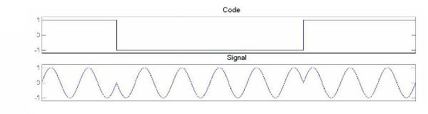
The measurement of a phase is a distance measurement: 2pi correspond to the wavelength, In other words approximately 3 cm in the band X. The problem is that it is a precise distance measurement modulo the wavelength.

The direction of a transmitter can be calculated by measuring the time delay between the arrival of the signal on two antennas with a known distance. Indeed the locus of points that generate the same delay is hyperbole whose foci are the two antennas. We then assimilates the hyperbole to their assymptotes because in general the transmitter is far.

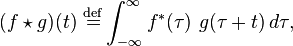
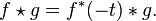
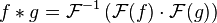
For measuring a delay we can make correlations between the signals received by an antenna and that received by the other, the signals are shifted in time by an antenna relative to another until one has the correlation. The time that has allowed this correlation is the offset of the arrival of the signal from both antennas.

We have our hyperbole, that is, 4-way, but if we do the same treatment with another pair of antennas we have 4 other directions and if we have well designed geometry of the two pairs only one direction shall be common to two doublets. So we have the direction of the transmitter. This is the DTOA treatment described in more detail in the first paragraph.

But it is not accurate. To improve accuracy we measure the signal phase to the arrival of the two antennas. We have seen that this was a distance measuring modulo the wavelength, the delay is also a measurement of distance by multiplying by the speed of light. The assembly of the two measurements provides a measure of precise distance. It can be converted into measure precise delay.

If the delay is accurately measured and the distance between the two antennas is also known precisely, we can deduce a precise direction of the transmitter. Antennas have known positions built, but they should not "move" with respect to the other, so interferometry is NOT recommended if the antennas are wingtip. It takes place on a rigid part of the plane if you do not want to lose the advantage of the accuracy of the measured delay.
 
In signal processing, the cross-correlation is a measure of the similarity of the two waveforms in accordance with a time lag applied to one of them. For continuous functions f and g, the cross-correlation is defined as:

3065b8e6462c3ac314880a44bb8c9b7c.png


where f * is the complex conjugate of f and t is time.

For example, if we consider two real functions and differing only by an unknown offset x. the cross-correlation can be used to find how much we must shift the x to the overlap. The formula involves calculating for each point x the product of two integral functions. When the functions overlap, product value is maximized. Indeed if the extreme values are superimposed they strongly contribute to the integral value that is positive or negative because the product of two negative numbers is positive.

If the functions are complex-valued, taking the conjugate is ensured that the extreme with imaginary components positively contribute to the integral.

The convolution of two real or complex functions f and g, is another function, which is usually rated "
945624babab691d999ca815ff8be85ec.png
" and is defined by:

fc96aa2dffc3af22dfd74570d4b55e8f.png


We have

e4b104e080ea0ded3f514ab0502c919b.png


This equality is used in signal processing to reduce processing time. Indeed the Fourier transform of a convolution product is obtained by multiplying the Fourier transforms of the functions and thus if f and g are square integrable then:

749a1677dd114c2b8d46d6c4a3c777b7.png


The main interest of calculating the convolution of Fourier transform is that these operations are less costly in time to a computer that the direct calculation of the integral. This formula will effectively calculate the cross-correlation of two signals or the autocorrelation of the same signal received at different times.

This specialized calculation was first performed by general computers, but you can now make massively parallel components dedicated to that sole function. For use in overall GPS receivers locate generated component of 16000 correlators:

http://d1.ourdev.cn/bbs_upload782111/files_35/ourdev_607138GSZQOV.pdf

I intend to show some possible applications, in SPECTRA and RBE2 AESA of these approach and technology.
 
The first application that comes to mind concerning the use of correlators which I mentioned in the previous post is that concerning the RWR. As we know nothing of the threat we have to watch all frequencies and all delays in the time limit of propagation of light between the dipole antenna that is used. The frequency / time plane is cut into individual box in which the correlation will be tested.

More cutting is fine, and more detection will be sensitive : in fact the superposition is never perfect because time is discrete and frequency undergoes a different Doppler effect for each antenna. More cutting is fine, more the overlay will be of quality, and the higher the correlation will make a strong signal.

If we had only one correlator (or general computer), it would make the calculation successively for all times and all frequencies, which could take more time than the acquisition and would be forced to enlarge the grid and therefore reduce sensitivity. We see the value of having a chip with 16,000 correlators. Nothing prohibits also to use several such chip.

To achieve good accuracy in measuring the direction, there are two techniques you can increase the distance between the antennas, but we then must increase the size of the grid element (time / frequency) to be measured. It can also be a measure of the signal phase, which will give an accurate delay and therefore an accurate direction.

But it's not just the RWR. The radar can also use this technique. Indeed a radar knows very well what pulse he sent, so it is well placed to test the return using the technique described above. As what he seeks is accurate it will be able to spend a lot of time (doing fine cutting) for detection.

For example, if the radar used a long pulse, to distribute energy over time, and increase its discretion, the detection of return with correlators is equivalent to compress the pulse, as if it was short, and with the same energy.
 
To arrive at application level, there is still a need of some little preparation. For this I will explain by relying on examples from navigation satellites. We have to realize that from the point of view of detection performance, navigation satellite receivers are extraordinary. The satellites are at 20,000 km, the emiting power is in the range of a few watts, the receivers have no huge antennas, and yet it works.

The detection method is the one I have described, but for this to be effective we must encode the signal with codes called "gold" because they give a strong self correlation and low cross correlation. The coding is thus carried out:

Code-signal.jpg


A pure frequency would not allow this correlation research principle. In addition to encoding signal may include some data:

GPS-code-data.jpg

And this can be helpful as we shall see.

Why explain it? We must first understand that radar, communications, jammers and navigation satellites use electromagnetic techniques that can converge; signal and military navigation satellite has very interesting features.

First, we know how to limit its use to the allies, we know how to encrypt the signal so that it is useless to those who do not have the key. You should understand that I will not say more. We also know how to protect it against jamming, spoofing, ... and all the electronic warfare. What is astonishing because it is an extremely weak signal.
 
The upstream study TRAGEDAC, notified in 2010, aims to achieve the Rafale and future combat drones passive 3D location network in order to more easily establish a tactical situation, and to improve the responsiveness of fire control and coordination in the patrol. The solution must operate in real time using information from sensors networked aircraft.

http://www.defense.gouv.fr/actualit.../les-materiels-presentes/etude-amont-tragedac

The idea is to increase the accuracy of locating an enemy using non-emissive methods (Spectra and frontal sector optronics) and sharing the information collected in a patrol, for example via Link 16, particularly to determine the distance of the target which is the most difficult data to estimate, when limiting itself to only use passive means. This is a pure software modification but which according to the DGA, is especially complex to implement from the point of view of data synchronization between devices. First test flights are expected to start by year 2013 end to collect data.

http://www.air-cosmos.com/defense/le-bourget-2013-la-defense-a-l-honneur.html

What can be imagined as a solution? The easiest way seems to use the link 16. But on link 16 we transmit the tracks, indeed ESM is a bearing track, but if we do nothing more we will lose many measures since the track must be maintained by the participating unit in the best position from the perspective of the "track quality". This is not what we want, we want measures from the different planes to allow triangulation, we want to feed a Kalman filter with all that, so it may give us a target position, course and speed.We certainly do not want to lose measures.

If there was only a track that would be relatively easy, but as there are several, you must be able to associate the ESM bearings and the targets that you want to follow without error. For the Kalman filter to work well, it will date measurements with accurate and common time base as explained in a previous post. To assign the right measures at the target it will rely on technical analysis of the signal made by each aircraft.

Is that the link 16 is adapted to do this? The problem is that you can not make it evolve unilaterally, if we assume that we need a new "object" "Measure" to implement the new treatments, it may be easier to use another link than to obtain a modification of the L16.

And then the link 16 is not passive! The proof is that the patrol planes are supposed to receive it.

Then there is in SPECTRA, the possibility of directional jamming with AESA antenna and these antennas are placed so that they cover 360 °. We have the hardware to create a dedicated link that will be discreet because Directive.

But we can go even further, we may want to make self-correlation between an antenna and a plane of another aircraft. Having a dedicated link will facilitate this process because we will not be constrained by the protocol of the link 16. The fact significantly increase the distance between the antennas will improve the accuracy, beyond even that which is possible with interferometry because the position error (on the order of 5 m) will be small with respect to the distance of the antennas. As against the treatment must take into account a larger range of delays which increases the computing power required to stay in real time.

The fact also that the antennas are remote makes significant difference Doppler and further increases the volume of treatments to achieve. However the Doppler is a measure of the radial velocity, which can greatly facilitate the convergence of the Kalman filter.

Once we realized Tragedac, we realized 80% of a multistatic Radar. We assume AESA radar are used as emitters and PESA as passive receivers. The AESA radar emits and transmits over the dedicated link, data allowing PESA to build a replica of the signal, it can thus detect the direct signal (using Spectra for example) and the reflected (with PESA antenna) by correlation with the replica he built. As we have seen, the signal is encoded and can contain data. The signal may therefore hold the position of the emitter (x, y, z, t) and the orientation of its antenna.

Delay on the signal reflected from the date of emission defines a location position of the target which is an ellipse and the orientation of the antenna defines a bearing whose intersection with the ellipse gives the position of the target . Of course the common time base is still that of the satellite navigation system.
 
F22_vs_Rafale_dogfight_video.mp4_000134434.jpg


.

BFM between French Rafale/F22 Raptor - ATLC 2009


BFM_between_French_RafaleF22_Raptor_-_ATLC_2009_on_Vimeo.mp4_000002200.jpg


Actual video begins at 2:15. Rafale’s speed at beginning is 360 knots, and it is turning at cca 6 g.

BFM_between_French_RafaleF22_Raptor_-_ATLC_2009_on_Vimeo.mp4_000028720.jpg


It continues turning, with a bit of rolling, at 4-6 g, entire time keeping the speed above 300 knots and even getting it up to 500 before executing a semi-vertical turn and achieving over 8 g at 2:46.

BFM_between_French_RafaleF22_Raptor_-_ATLC_2009_on_Vimeo.mp4_000034560.jpg


BFM_between_French_RafaleF22_Raptor_-_ATLC_2009_on_Vimeo.mp4_000038200.jpg


At 2:49, F-22 flies into the view from right, and Rafale rolls, pulling up and gaining altitude afterwards, loosing F-22 at 2:54.

BFM_between_French_RafaleF22_Raptor_-_ATLC_2009_on_Vimeo.mp4_000049280.jpg


BFM_between_French_RafaleF22_Raptor_-_ATLC_2009_on_Vimeo.mp4_000049920.jpg


BFM_between_French_RafaleF22_Raptor_-_ATLC_2009_on_Vimeo.mp4_000050240.jpg


Afterwards, Rafale turns around, pointing nose towards the F-22 flying below it at 3:04 and achieving a lock-on and a missile launch at 3:07.
 
BFM_between_French_RafaleF22_Raptor_-_ATLC_2009_on_Vimeo.mp4_000055720.jpg


BFM_between_French_RafaleF22_Raptor_-_ATLC_2009_on_Vimeo.mp4_000067680.jpg


BFM_between_French_RafaleF22_Raptor_-_ATLC_2009_on_Vimeo.mp4_000067920.jpg


Rafale’s speed at time of missile launch was 157 kts. At 3:10, gun targeting outline appears. At 3:23, F-22 is again in view, though it does not result in either gun or missile kill, and Rafale pilot does not roll to follow the F-22.


BFM_between_French_RafaleF22_Raptor_-_ATLC_2009_on_Vimeo.mp4_000077240.jpg


BFM_between_French_RafaleF22_Raptor_-_ATLC_2009_on_Vimeo.mp4_000091440.jpg


BFM_between_French_RafaleF22_Raptor_-_ATLC_2009_on_Vimeo.mp4_000106320.jpg


Rafale continues turning until nose is pointed upwards at 3:35, after which it turns towards the ground. At 3:59, it again has nose pointed mostly upwards, and turns sideways towards the ground.
 
BFM_between_French_RafaleF22_Raptor_-_ATLC_2009_on_Vimeo.mp4_000115520.jpg


BFM_between_French_RafaleF22_Raptor_-_ATLC_2009_on_Vimeo.mp4_000123920.jpg


BFM_between_French_RafaleF22_Raptor_-_ATLC_2009_on_Vimeo.mp4_000125320.jpg


BFM_between_French_RafaleF22_Raptor_-_ATLC_2009_on_Vimeo.mp4_000126040.jpg


BFM_between_French_RafaleF22_Raptor_-_ATLC_2009_on_Vimeo.mp4_000131120.jpg


At 4:10, F-22 is again in sight, and Rafale turns inside the F-22. At 4:20 lock-on is achieved but Rafale pilot does not call a missile kill, with low speed warning appearing at 4:26 (speed cca 120 kts) and disappearing at 4:28, to reappear at 4:29; low fuel warning appears at 4:26.
 
BFM_between_French_RafaleF22_Raptor_-_ATLC_2009_on_Vimeo.mp4_000155280.jpg


BFM_between_French_RafaleF22_Raptor_-_ATLC_2009_on_Vimeo.mp4_000156720.jpg


BFM_between_French_RafaleF22_Raptor_-_ATLC_2009_on_Vimeo.mp4_000156960.jpg


BFM_between_French_RafaleF22_Raptor_-_ATLC_2009_on_Vimeo.mp4_000157200.jpg


BFM_between_French_RafaleF22_Raptor_-_ATLC_2009_on_Vimeo.mp4_000157640.jpg


BFM_between_French_RafaleF22_Raptor_-_ATLC_2009_on_Vimeo.mp4_000157880.jpg


BFM_between_French_RafaleF22_Raptor_-_ATLC_2009_on_Vimeo.mp4_000158360.jpg


BFM_between_French_RafaleF22_Raptor_-_ATLC_2009_on_Vimeo.mp4_000158560.jpg


At 4:35, Rafale is turing towards the ground and speed has gone above 100 knots again. Rafale gets F-22, which has regained the energy, in its view at 4:40; F-22 is turning hard for next few seconds, and at 4:50, Rafale is directily behind the F-22 and has achieved the missile lock.
 
BFM_between_French_RafaleF22_Raptor_-_ATLC_2009_on_Vimeo.mp4_000159080.jpg


BFM_between_French_RafaleF22_Raptor_-_ATLC_2009_on_Vimeo.mp4_000166320.jpg


At 4:54, F-22 flies out of view and Rafale makes no attempt to follow; at 5:00, Rafale has returned to level flight, and at 5:23 Rafale pilot is heard requesting termination of engagement.

As exercise was guns-only, missile kills were not counted. It is still clear that French statement about Rafale achieving several missile kills against the F-22 is correct. At around 4:40-40:50, Rafale seems to have missed an opportunity for a gun kill, but is otherwise mostly in control of the fight, with F-22 never gaining the initiative. Video does show that Rafale has good low-speed maneuvering performance and is capable of regaining lost energy at adequate rate.

Rafale__India Defence Forum 토론 자료_(USA 미국 UK 영국 Eurofighter Typhoon, F-22, F-35) vs (FRANCE 프랑스 Rafale) vs (RUSIA 러시아 INDIA 인도 PAK-FA)... = (4 gen 세대, 4+ gen 세대, 5 gen 세대 타령, Stealth 스텔스 타령 전투기들) vs (Rafale)... 그 끝나지 않은 이야기_2013.12.18~2014.01.16 : 네이버 블로그
 
Last edited:
French Pilots Over Libya Decline US Intel; Clearance Just Too Slow
When asked why French air forces were not taking advantage of advanced manned and unmanned targeting imagery, pilots responded that it took too much time to coordinate with NATO commanders at the Combined Air Operations Center (CAOC) in northern Italy. Instead, pilots deferred to using their own reconnaissance pods. Pilots reported rejecting Predator drone images for targeting purposes, saying its imagery took too long to get cleared through the CAOC.
French Pilots Over Libya Decline US Intel; Clearance Just Too Slow « Breaking Defense - Defense industry news, analysis and commentary

SPECTRA and CARBONE

Carbone is a demonstrator of an escort-jamming system where dedicated platforms and crews is replaced by a combination of integrated systems featuring a solid-state phased-array jammer, with very high transmitted power and real-time steering of multi-beam . This is fitted in an automatic pod carried by a multirole fighter for the stand-in/escort jamming mission.

Carbone is significantly more powerful than existing or upgraded offensive-jamming pods. Carbone use DRFM receiver and real-time geolocation algorithms, such as those implemented in Spectra.

Operational trials have demonstrated Carbone's effectiveness, and particularly its capability to jam through scattered lobes (NATO MACE X field trials in August 2000).

spectra-tesbed1.jpg


I understand that the philosophy of Carbone was to analyse incoming signal with interferometry , locate the emitter, duplicate the signal with DRFM, and send it several time to the emitter. So it's not just noise as in general for offensive jammer.

But remember that Carbone was just a demonstrator, perhaps the objective was just to demonstrate a real time capability to duplicate signal. Because if you are able to do that in real time, no doubt that you will be able to slighty modify the replica to make smarter jam.

Finally technologies are the same as SPECTRA : DRFM, localisation, but the power is bigger and the jamming approach is less smart. The corresponding operational system is perhaps SPECTRA.

How does SPECTRA work?

First you need to know perfectly the "signature" of your own aircraft. Due to the complexity of the SPECTRA traitment, Rafale start to simplify its signature: the aircraft is designed so that its untreated radar signature is concentrated in a few strong "spikes," which are then "attenuated" by the selective use of RAM. The collection of these few strong spikes are the "model" of Rafale.

Second it would be nice to cancel the reflected radar signal. The original incoming signal from the radar will be reflected from the spikes. Each spikes will produce an individual reflection with its own, often unique, amplitude and phase. The return signal, picked up by the radar, would look somewhat chaotic, consisting of background noise and "spikes". By removing these "spikes" from the radar screen the aircraft may blend in with the background noise, which is normally ignored by the radar operators.

If you look at where are SPECTRA active antenna, surprisingly they are close to areas that can generate spikes.

To remove these spikes the aircraft, when painted by a radar, transmits a signal which mimics the echo that the radar will receive from the spikes, but one half-wavelength out of phase, so that the radar sees no return from them. The advantage of this technique is that it uses very low power, compared with conventional EW, and provides no clues to the aircraft's presence; the challenge is that it requires very fast processing. This fast processing was demonstrated by Carbone.

untitled.png


- A Rafale heading north locked with its passive sensors a target "M2T" located South-South/East ,

48 nautical miles behind him. (with a time to target = 6'14'') .

- 286°/50 kt should indicate the wind.

- The green arrow may indicate the current move of the locked target or perhaps the direction

where the missile will be launched taking into account several factors

(estimated speed and move of the target , the Rafale, the wind... ).

- The green color of the arrow and of "PKG_DA" could indicate that a firing solution is ok and

the red symbol below could indicate a weapon (Mica) available (or not) for firing.
 

Back
Top Bottom