The only thing you've demonstrated is how much of a fraud you are.

Question: does anyone see a problem with ptldM3's ray trace?
When you guys see the words 'corner reflector', did it occurred to anyone that it begs the question of whether there are any other types of reflectors? Probably not. Not one of you guys have proven himself to be sufficiently self critical of what he know and what he does not know.
In long range communication, the reflector antenna is the most frequently used where high gain are required. Of the reflector class, the parabolic reflector, aka 'dish', is the most prominent.
Other reflectors are:
- Parabolic cylinder
Projects-doc-282-v1: Directivity of a Parabolic Cylinder Antenna
The 21 cm project is based on a parabolic cylinder antenna with receivers placed periodically along the focus line of the antenna.
- Parabolic torus
The parabolic torus reflector antenna
A multiple-beam antenna in which the reflecting surface is a parabolic torus can be used to scan an arc of over 90-deg with a performance virtually unchanged over the entire range.
- Spherical
http://ieeexplore.ieee.org/xpls/abs_all.jsp?arnumber=1144675&tag=1
A study is made of spherical reflectors for use as wide-angle scanning antennas.
Then there is the multiple reflectors type but the designs under this are not applicable to our discussion relating to radar cross section (RCS). The three above and the corner reflector are of single reflector type and are often found on any aircraft's body. Each structure create a different radiation pattern from the others. If there is a tranmitting antenna like a simple dipole that is placed in front of a reflector, the entire assembly is called an 'active reflector antenna'.
A circular active reflector atenna (CARA), energy distribution calculations, and an experimental test :: Institutional Repository
Such a device is called a circular active reflector antenna (CARA),...
Without a transmitting antenna, the label is "passive reflector antenna'.
Passive reflectors
This document deals with the 'antenna-passive reflector' association used in microwave links.
From an RCS control perspective, we look for the passive reflector type such as the 90 deg corner reflector created by the vertical and horizontal stabilators joining.
In the above illustration, the angle between the sides is called the 'aperture angle'.
IEEE Xplore - Abstract Page
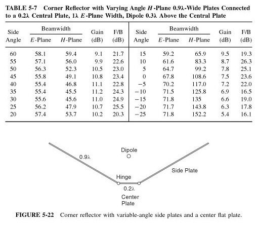
An experimental comer reflector was erected at the Table Mesa antenna range near Boulder. The aperture angle of this antenna was made adjustable to any value between 20 and 180 degrees. The widths and lengths of the reflecting surfaces were each adjustable from 0.4 to 5.0 wavelengths. Measurements of gain were made for numerous combinations of lengths and widths of reflecting surfaces. These measurements were made with a half-wave dipole in the first, second and third maximum positions. The aperture angle was adjusted to maximize the gain. The principal results are presented in the form of contours of constant gain plotted for a range of widths and lengths of reflecting surfaces from 0.4 to 5.0 wavelengths. These graphs should be useful to a designer of corner-reflector antennas.
The highlighted are significant. First, it mean the phrase 'corner reflector' is not restricted to the 90 deg type. Second, it mean altering the aperture angle affects gain and reflected power. This paper is decades old and the information within have been used by radar testing specialists the world over whenever they need to design and build target corner reflectors for radar testing -- what I used to do after the USAF.
We can design these target enhancers to help a weapon's radar to hit a ship or even a
SPECIFIC part of a ship. The greater the departure from 90 deg by the aperture angle, the weaker the reflected signals, and the greater the odds of a miss. That is how we learn the effectiveness of a weapon's radar system under a variety of conditions, from natural such as weather to man made such as chaff. Inside the corner reflector, the main beam may not return to source direction but the side lobes will approach each side differently. We can calculate how the side lobes will reflect and whether they can be detected or not. Then we build to verify.
Before 'stealth', in aviation, usually when a new discovery is made or a new technology developed, a new aircraft design will have a lead from the appropriate technology branch. For example, when the 'area rule' was discovered, aerodynamicists with their new delta wing designs dominated the 'Century' series. When the jet engine was new, the Propulsion branch dominated with the P-80 and later with the F15 and F-16 with their powerful engines that skewed the thrust to weight ratio. For the A-10, the Armament branch dominated, they essentially told everyone else to design their systems to support the Vulcan cannon.
With 'stealth' starting with the F-117, the Electrical Engineering branch took the lead and have been ever since. As far as the RCS control engineer is concerned, every aircraft is a conglomeration of different reflectors of different sizes and shapes. Every structure must have the EE's input. Granted, to keep the design flight worthy, aeerodynamics must take priority, but now the aerodynamicists cannot ignore the EE and often times must concede to the EE's demands.
So for RCS control, the rules from Electrical Engineering are:
- Avoid the corner reflector.
- If not possible, then avoid the 90 deg type.
The first rule basically say
ALL reflectors are evil. Does not matter if it is corner or parabolic. The corner type just happens to be the most common, but any structure that focuses and concentrate reflected signals unidirectionally is an evil structure because there is a chance that just a little will be enough to give you away. So do not have it anywhere.
The second rule basically say that since aerodynamic necessity trumps RCS considerations, then avoid the 90 deg corner reflector because it is the best concentrator of reflected signals. So if you must have the corner reflector, avoid the 90 deg type and use it sparingly.
The B-2 is the first rule. Everything else, including the J-20, is the second rule. From the side view, the F-22 have one corner reflector, where the vertical stabilator created it with a part of the horizontal stabilator and with a part of the wing. From the side view, the J-20 have two corner reflectors: one from the vertical and horizontal stabilators, one from the ventral and horizontal stabilator.
So when I said that the F-22's flight control surfaces created corner reflectors and the ID village idiot laughed because he thought he did a 'gotcha' on me, it revealed that your little pet is a fraud when he said he has aviation experience or 'study' but refuses to tell us what.
I do not expect you Chinese boys to believe what I posted above despite the sources I presented to show the items and terminologies are legit. I have seen enough of your guys' behaviors to know the lot of you is sufficiently arrogant and full of yourselves to think that if you have never heard of <something> it does not exist, no matter how much proofs and logic are in front of you. You guys' disdain for experience is unique to you while everyone else appreciates it when they know they do not have it. For the Chinese members here, it is inconceivable that
THEY COULD BE WRONG. You would rather twist and abuse the laws of nature than to concede to your errors.


