What's new

Fundamentals of Stealth Design & Concepts of RCS Reduction

What is Stealth Technology?

Stealth or low observability (as it is scientifically known) is one of the most misunderstood and misinterpreted concepts in military aviation by the common man. Stealth aircraft are considered as invisible aircraft, which dominate the skies. With an additional boost from Hollywood action movies, stealth is today termed as the concept invincibility rather than invisibility. Though, the debate still continues on whether stealth technology can make an aircraft invincible it was found that stealth aircraft are detectable by radar.

The motive behind incorporating stealth technology in an aircraft is not just to avoid missiles being fired at is but also to give total deniability to covert operations. This is very much useful to strike targets where it is impossible to reach. Thus we can clearly say that the job of a stealth aircraft pilot is not to let others know that he was ever there.


What is Stealth?

In simple terms, stealth technology allows an aircraft to be partially invisible to Radar or any other means of detection. This doesn't allow the aircraft to be fully invisible on radar. Stealth technology cannot make the aircraft invisible to enemy or friendly radar. All it can do is to reduce the detection range or an aircraft. This is similar to the camouflage tactics used by soldiers in jungle warfare. Unless the soldier comes near you, you can't see him. Though this gives a clear and safe striking distance for the aircraft, there is still a threat from radar systems, which can detect stealth aircraft.

The Russian 1R13 radar system is very much capable of detecting the F-117 "Night Hawk" stealth fighter. There are also some other radar systems made in other countries, which are capable of detecting the F-117. Duringhttp://www.totalairdominance.50megs.com the Gulf war the Iraqis were able to detect the F-117 but failed to eliminate its threat because of lack of coordination. The most unforgettable incident involving the detection and elimination of a stealth aircraft was during the NATO air-war over Yugoslavia. This was done by a Russian built "not so advanced" SAM (possibly the SA-3 or SA-6). The SAM system presumably used optical detection for target acquisition in the case.


How does Stealth technology work?

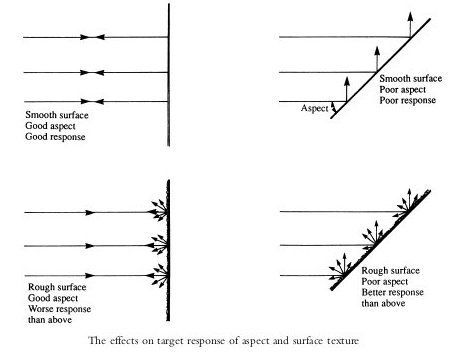
The concept behind the stealth technology is very simple. As a matter of fact it is totally the principle of reflection and absorption that makes aircraft "stealthy". Deflecting the incoming radar waves into another direction and thus reducing the number of waves does this, which returns to the radar. Another concept that is followed is to absorb the incoming radar waves totally and to redirect the absorbed electromagnetic energy in another direction. What ever may be the method used, the level of stealth an aircraft can achieve depends totally on the design and the substance with which it is made of.


RAS

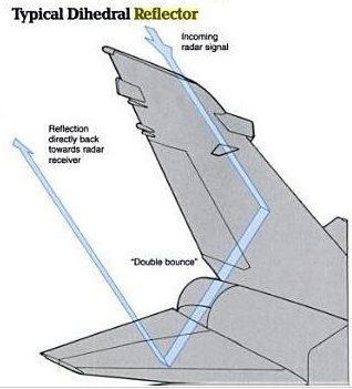
RAS or Radar absorbent surfaces are the surfaces on the aircraft, which can deflect the incoming radar waves and reduce the detection range. RAS works due to the angles at which the structures on the aircraft's fuselage or the fuselage itself are placed. These structures can be anything from wings to a refueling boom on the aircraft. The extensive use of RAS is clearly visible in the F-117 "Night Hawk". Due to the facets (as they are called) on the fuselage, most of the incoming radar waves are reflected to another direction. Due to these facets on the fuselage, the F-117 is a very unstable aircraft.

The concept behind the RAS is that of reflecting a light beam from a torch with a mirror. The angle at which the reflection takes place is also more important. When we consider a mirror being rotated from 0o to 90o, the amount of light that is reflected in the direction of the light beam is more. At 90o, maximum amount of light that is reflected back to same direction as the light beam's source. On the other hand when the mirror is tilted above 90o and as it proceeds to 180o, the amount of light reflected in the same direction decreases drastically. This makes the aircraft like F-117 stealthy.


RAM

Radar absorbent surfaces absorb the incoming radar waves rather than deflecting it in another direction. RAS totally depends on the material with which the surface of the aircraft is made. Though the composition of this material is a top secret. The F-117 extensively uses RAM to reduce its radar signature or its radar cross section.

The RAS is believed to be silicon based inorganic compound. This is assumed by the information that the RAM coating on the B-2 is not waterphttp://www.totalairdominance.50megs.comroof. This is just a supposition and may not be true. What we know is that the RAM coating over the B-2 is placed like wrapping a cloth over the plane. When radar sends a beam in the direction of the B-2, the radar waves are absorbed by the plane's surface and is redirected to another direction after it is absorbed. This reduces the radar signature of the aircraft.


IR

Another important factor that influences the stealth capability of an aircraft is the IR (infrared) signature given out by the plane. Usually planes are visible in thermal imaging systems because of the high temperature exhaust they give out. This is a great disadvantage to stealth aircraft as missiles also have IR guidance system. The IR signatures of stealth aircraft are minute when compared to the signature of a conventional fighter or any other military aircraft.

If reducing the radar signature of an aircraft is tough, then reducing the IR signature of the aircraft is tougher. It will be like flying a plane with no engines. The reduced IR signature totally depends on the engine and where the engine is placed in an aircraft.

Engines for stealth aircraft are specifically built to have a very low IR signature. The technology behind this is top secret like others in stealth aircraft. Another main aspect that reduces the IR signature of a stealth aircraft is to place the engines deep into the fuselage. This is done in stealth aircraft like the B-2, F-22 and the JSF. The IR reduction scheme used in F-117 is very much different from the others. The engines are placed deep within the aircraft like any stealth aircraft and at the outlet, a section of the fuselage deflects the exhaust to another direction. This is useful for deflecting the hot exhaust gases in another direction.


Methods of avoiding detection

There are some more methods by which planes can avoid detection. These methods do not need any hi-tech equipment to avoid detection. Some of them have been used for years together by pilots to avoid detection.

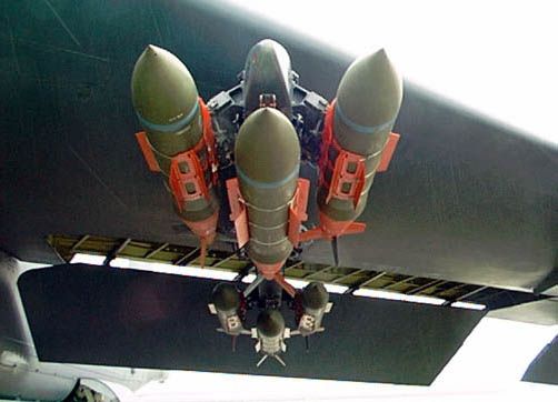
One of the main efforts taken by designers of the stealth aircraft of today is to carry the weapons payload of the aircraft internally. This has shown that carrying weapons internally can considerably decrease the radar cross-section of the aircraft. Bombs and Missiles have a tendency to reflect the incoming radar waves to a higher extent. Providing missiles with RAM and RAS is an impossible by the cost of these things. Thus the missiles are carried in internal bombays which are opened only when the weapons are released.

Aircraft has used another method of avoiding detection for a very long time. Radars can use the radar waves or electro-magnetic energy of planes radar and locate it. An aircraft can remain undetected just by turning the radar off.

In case of some of the modern stealth aircraft, it uses its wingman in tandem to track its target and destroy it. It is done in the following way. The fighter, which is going to attack moves forward, the wingman (the second aircraft) on the other hand remains at a safe distance from the target which the other fighter is approaching. The wingman provides the other fighter with the radar location of the enemy aircraft by a secured IFDL (In Flight Data Link). Thus the enemy radar is only able to detect the wingman while the attacking fighter approaches the enemy without making any sharp turns. This is done not to make any sudden variations in a stealth aircraft's radar signature. Thus the fighter, who moves forward, is able to attack the enemy without being detected.


Plasma Stealth

Plasma stealth technology is what can be called as "Active stealth technology" in scientific terms. This technology was first developed by the Russians. It is a milestone in the field of stealth technology. The technology behind this not at all new. The plasma thrust technology was used in the Soviet / Russian space program. Later the same engine was used to power the American Deep Space 1 probe.

In plasma stealth, the aircraft injects a stream of plasma in front of the aircraft. The plasma will cover the entire body of the fighter and will absorb most of the electromagnetic energy of the radar waves, thus making the aircraft difficult to detect. The same method is used in Magneto Hydro Dynamics. Using Magneto Hydro Dynamics, an aircraft can propel itself to great speeds.

Plasma stealth will be incorporated in the MiG-35 "Super Fulcrum / Raptor Killer". This is a fighter which is an advanced derivative of the MiG-29 "Fulcrhttp://www.totalairdominance.50megs.comum / Baaz". Initial trials have been conducted on this technology, but most of the results have proved to be fruitful.


Detection methods for stealth aircraft

Whenever a technology is developed for military purposes, another technology is also developed to counter that technology. There are strong efforts to develop a system that can counter the low obervability of the fifth generation stealth aircraft. There are ways of detection and elimination of a low observable aircraft but this doesn't give a 100% success rage at present.

On a radar screen, aircraft will have their radar cross sections with respect to their size. This helps the radar to identify that the radar contact it has made is an aircraft. Conventional aircraft are visible on the radar screen because of its relative size. On the other hand, the relative size of a stealth aircraft on the radar screen will be that of a large bird. This is how stealth aircraft are ignored by radar and thus detection is avoided.

A proven method to detect and destroy stealth aircraft is to triangulate its location with a network of radar systems. This was done while the F-117 was shot down during the NATO offensive over Yugoslavia.

A new method of detecting low observable aircraft is just over the horizon. Scientists have found a method to detect stealth aircraft with the help of microwaves similar to the ones emitted by the cell phone towers. Nothing much is known about this technology, but the US military seems to be very keen about doing more research on this.


Disadvantages of stealth technology

Stealth technology has its own disadvantages like other technologies. Stealth aircraft cannot fly as fast or is not maneuverable like conventional aircraft. The F-22 and the aircraft of its category proved this wrong up to an extent. Though the F-22 may be fast or maneuverable or fast, it can't go beyond Mach 2 and cannot make turns like the Su-37.

Another serious disadvantage with the stealth aircraft is the reduced amount of payload it can carry. As most of the payload is carried internally in a stealth aircraft to reduce the radar signature, weapons can only occupy a less amount of space internally. On the other hand a conventional aircraft can carry much more payload than any stealth aircraft of its class.

Whatever may be the disadvantage a stealth aircraft can have, the biggest of all disadvantages that it faces is its sheer cost. Stealth aircraft literally costs its weight in gold. Fighters in service and in development for the USAF like the B-2 ($2 billion), F-117 ($70 million) and the F-22 ($100 million) are the costliest planes in the world. After the cold war, the number of B-2 bombers was reduced sharply because of its staggering price tag and maintenance charges. There is a possible solution for this problem. In the recent past the Russian design firms Sukhoi and Mikhoyan Gurevich (MiG) have developed fighters which will have a price tag similar to that of the Su-30MKI. This can be a positive step to make stealth technology affordable for third world countries.


Stealth aircraft of yesteryears, today and tomorrow

Stealth technology is a concept that is not at all new. During the Second World War, allied aircraft used tin and aluminum foils in huge numbers to confuse German radar installations. This acted as a cover for allied bombers to conduct air raids. This method was later used as chaffs by aircrafts to dodge radar guided missiles.

The first stealth aircraft was the F-117 developed by Lockheed Martin. It was a top-secret project developed by its Skunk Works unit. The F-117 was only revealed during the late 80s and then saw action in the Persian Gulf.

In due course of time the B-2 was developed as a successor to the B-2. Though both of them serve different purposes, the B-2 went a step ahead of the F-117. The B-2 was developed to deliver nuclear weapons and other guided and unguided bombs. On the other hand the F-117 was developed to deliver its precision laser guided bombs.

Another stealth aircraft, which made a lot of promises and in the end ended up in a trashcan, was the A-12. It was a fighter that was designed to replace the F-14 and F-18 in the future. The capabilities of this aircraft were boasted to such an extent that the project ended up in a big mess. Billions of dollars were wasted for nothing.

Stealth technology became famous with the ATF contest. The Boeing-Lockheed YF-22 and the McDonell Douglas-Grumman YF-23 fought for the milti-billion contract to build the fighter that would take the USAF into the fifth generation fighter era. The Boeing-Lockheed won the contract and the F-22 was approved to be the replacement for the F-15 "Eagle" interceptor.

America now has a competitors, Russia decided to respond to the development of the F-22 by making the Su-47 (S-37) "Berkut" and the MiG-35 "Super Fulcrum / Raptor Killer". These fighters were developed by the two leading aviation firms in Russia Sukhoi and Mikhoyan Gurevich (MiG). The future of these projects totally depends on the funding which will be provided to the Russian defense sector. There are some hopes of increase in the funding to these projects as countries like India have started providing funds and technical assistance for these projects.

Another competition that soon came into the spotlight after the ATF competition was the JSF. This time Boeing developed the X-32 and the Lockheed martinhttp://www.totalairdominance.50megs.com its X-35. With the experience gained from developing the F-22, they were tasked with making a replacement for the F-16. This saw great technological advances, as they had to make the first operational supersonic VSOL aircraft. Lockheed martin took the technical assistance of Russian scientists who developed the Yak-141. The Yak-141 is the first supersonic VSTOL aircraft. In the end the Lockheed team with its X-35 won the contract and the fighter was re-designated as the F-35.

Many projects remain over the horizon that will use stealth technology as its primary capability. They come from some of the most unlikely contenders. These projects include the Euro JSF, which will be designed by the team that developed the EF-2000. Russia is stepping forward with its LFS project with the S-54 and other designs. Two new entries into this field will be India and China. India will be introducing its MCA, which is a twin engine fighter without vertical stabilizers. This fighter will use thrust vectoring instead of rudders. China will be introducing the J-12 (F-12/XXJ). This http://www.totalairdominance.50megs.comis a fighter that is similar to the F-22.


Future of stealth technology

Stealth technology is clearly the future of air combat. In the future, as air defense systems grow more accurate and deadly, stealth technology can be a factor for a decisive by a country over the other. In the future, stealth technology will not only be incorporated in fighters and bombers but also in ships, helicopters, tanks and transport planes. These are evident from the RAH-66 "Comanche" and the Sea Shadow stealthttp://www.totalairdominance.50megs.comh ship. Ever since the Wright brothers flew the first powered flight, the advancements in this particular field of technology has seen staggering heights. Stealth technology is just one of the advancements that we have seen. In due course of time we can see many improvements in the field of military aviation which would one-day even make stealth technology obsolete


.::What is Stealth Technology?::.
 
How does stealth technology work?

The article How Radar Works talks about the basic principles of a radar system. The idea is for the radar antenna to send out a burst of radio energy, which is then reflected back by any object it happens to encounter. The radar antenna measures the time it takes for the reflection to arrive, and with that information can tell how far away the object is.

The metal body of an airplane is very good at reflecting radar signals, and this makes it easy to find and track airplanes with radar equipment.

The goal of stealth technology is to make an airplane invisible to radar. There are two different ways to create invisibility:

* The airplane can be shaped so that any radar signals it reflects are reflected away from the radar equipment.
* The airplane can be covered in materials that absorb radar signals.

Most conventional aircraft have a rounded shape. This shape makes them aerodynamic, but it also creates a very efficient radar reflector. The round shape means that no matter where the radar signal hits the plane, some of the signal gets reflected back:

stealth-1a.jpg


A stealth aircraft, on the other hand, is made up of completely flat surfaces and very sharp edges. When a radar signal hits a stealth plane, the signal reflects away at an angle, like this:

stealth-2a.jpg


In addition, surfaces on a stealth aircraft can be treated so they absorb radar energy as well. The overall result is that a stealth aircraft like an F-117A can have the radar signature of a small bird rather than an airplane. The only exception is when the plane banks -- there will often be a moment when one of the panels of the plane will perfectly reflect a burst of radar energy back to the antenna.

HowStuffWorks "How does stealth technology work?"


Factors that affect RCS

Size

As a rule, the larger an object, the stronger its Radar reflection and thus the greater its RCS. Also, Radar of one band may not even detect certain size objects. For example. 10 cm (S-band Radar) can detect rain drops but not clouds whose droplets are too small.

Material

Materials such as metal are strongly radar reflective and tend to produce strong signals. Wood and cloth (such as portions of planes and balloons used to be commonly made) or plastic and fibreglass are less reflective or indeed transparent to Radar making them suitable for radomes. Even a very thin layer of metal can make an object strongly radar reflective. Chaff is often made from metallised plastic or glass (in a similar manner to metallised foils on food stuffs) with microscopically thin layers of metal.
Also, some devices are designed to be Radar active, such as Radar antennae and this will increase RCS.


Radar absorbent paint

The SR-71 Blackbird and other planes were painted with a special "iron ball paint". This consisted of small metallic-coated balls. Radar energy is converted to heat rather than being reflected.

Shape, directivity and orientation

The surfaces of the F-117A are designed to be flat and very angled. This has the effect that Radar will be incident at a large angle (to the normal ray) that will then bounce off at a similarly high reflected angle; it is forward-scattered. The edges are sharp to prevent there being rounded surfaces. Rounded surfaces will often have some portion of the surface normal to the Radar source. As any ray incident along the normal will reflect back along the normal this will make for a strong reflected signal.
From the side, a fighter plane will present a much larger area than the same plane when viewed from the front. All other factors being equal, the plane will have a stronger signal from the side than from the front so the orientation between the Radar station and the target is important.

Smooth surfaces

The relief of a surface could contain indentations that act as corner reflectors which would increase RCS from many orientations. This could arise from open bomb-bays, engine intakes, ordnance pylons, joints between constructed sections, etc. Also, it can be impractical to coat these surfaces with radar-absorbent materials.


RCS Reduction

Purpose shaping

With purpose shaping, the shape of the target’s reflecting surfaces is designed such that they reflect energy away from the source. The aim is usually to create a “cone-of-silence” about the target’s direction of motion. Due to the energy reflection, this method is defeated by using Passive (multistatic) radars.
Purpose-shaping can be seen in the design of surface faceting on the F-117A Nighthawk stealth fighter. This aircraft, designed in the late 1970s though only revealed to the public in 1988, uses a multitude of flat surfaces to reflect incident radar energy away from the source. Yue suggests[citation needed] that limited available computing power for the design phase kept the number of surfaces to a minimum. The B-2 Spirit stealth bomber benefited from increased computing power, enabling its contoured shapes and further reduction in RCS. The F-22 Raptor and F-35 Lightning II continue the trend in purpose shaping and promise to have even smaller monostatic RCS.


Active cancellation

With active cancellation, the target generates a radar signal equal in intensity but opposite in phase to the predicted reflection of an incident radar signal (similarly to noise canceling ear phones). This creates destructive interference between the reflected and generated signals, resulting in reduced RCS. To incorporate active cancellation techniques, the precise characteristics of the waveform and angle of arrival of the illuminating radar signal must be known, since they define the nature of generated energy required for cancellation. Except against simple or low frequency radar systems, the implementation of active cancellation techniques is extremely difficult due to the complex processing requirements and the difficulty of predicting the exact nature of the reflected radar signal over a broad aspect of an aircraft, missile or other target.


Radar absorbent material

With radar absorbent material (RAM), it can be used in the original construction, or as an addition to highly reflective surfaces. There are at least three types of RAM: resonant, non-resonant magnetic and non-resonant large volume. Resonant but somewhat 'lossy' materials are applied to the reflecting surfaces of the target. The thickness of the material corresponds to one-quarter wavelength of the expected illuminating radar-wave (a Salisbury screen). The incident radar energy is reflected from the outside and inside surfaces of the RAM to create a destructive wave interference pattern. This results in the cancellation of the reflected energy. Deviation from the expected frequency will cause losses in radar absorption, so this type of RAM is only useful against radar with a single, common, and unchanging frequency. Non-resonant magnetic RAM uses ferrite particles suspended in epoxy or paint to reduce the reflectivity of the surface to incident radar waves. Because the non-resonant RAM dissipates incident radar energy over a larger surface area, it usually results in a trivial increase in surface temperature, thus reducing RCS without an increase in infrared signature. A major advantage of non-resonant RAM is that it can be effective over a wide range of frequencies, whereas resonant RAM is limited to a narrow range of design frequencies. Large volume RAM is usually resistive carbon loading added to fiberglass hexagonal cell aircraft structures or other non-conducting components. Fins of resistive materials can also be added. Thin resistive sheets spaced by foam or aerogel may be suitable for space craft.
Thin coatings made of only dielectrics and conductors have very limited absorbing bandwidth, so magnetic materials are used when weight and cost permit, either in resonant RAM or as non-resonant RAM.

Vehicle shape


The possibility of designing aircraft in such a manner as to reduce their radar cross-section was recognized in the late 1930s, when the first radar tracking systems were employed, and it has been known since at least the 1960s that aircraft shape makes a significant difference in detectability. The Avro Vulcan, a British bomber of the 1960s, had a remarkably small appearance on radar despite its large size, and occasionally disappeared from radar screens entirely. It is now known that it had a fortuitously stealthy shape apart from the vertical element of the tail. In contrast, the Tupolev 95 Russian long range bomber (NATO reporting name 'Bear') appeared especially well on radar. It is now known that propellers and jet turbine blades produce a bright radar image[citation needed]; the Bear had four pairs of large (5.6 meter diameter) contra-rotating propellers.
Another important factor is internal construction. Some stealth aircraft have skin that is radar transparent or absorbing, behind which are structures termed re-entrant triangles. Radar waves penetrating the skin get trapped in these structures, reflecting off the internal faces and losing energy. This method was first used on the Blackbird series (A-12 / YF-12A / SR-71).
The most efficient way to reflect radar waves back to the emitting radar is with orthogonal metal plates, forming a corner reflector consisting of either a dihedral (two plates) or a trihedral (three orthogonal plates). This configuration occurs in the tail of a conventional aircraft, where the vertical and horizontal components of the tail are set at right angles. Stealth aircraft such as the F-117 use a different arrangement, tilting the tail surfaces to reduce corner reflections formed between them. A more radical method is to eliminate the tail completely, as in the B-2 Spirit.
In addition to altering the tail, stealth design must bury the engines within the wing or fuselage, or in some cases where stealth is applied to an extant aircraft, install baffles in the air intakes, so that the turbine blades are not visible to radar. A stealthy shape must be devoid of complex bumps or protrusions of any kind; meaning that weapons, fuel tanks, and other stores must not be carried externally. Any stealthy vehicle becomes un-stealthy when a door or hatch opens.
Planform alignment is also often used in stealth designs. Planform alignment involves using a small number of surface orientations in the shape of the structure. For example, on the F-22A Raptor, the leading edges of the wing and the tail surfaces are set at the same angle. Careful inspection shows that many small structures, such as the air intake bypass doors and the air refueling aperture, also use the same angles. The effect of planform alignment is to return a radar signal in a very specific direction away from the radar emitter rather than returning a diffuse signal detectable at many angles.
Stealth airframes sometimes display distinctive serrations on some exposed edges, such as the engine ports. The YF-23 has such serrations on the exhaust ports. This is another example in the use of re-entrant triangles and planform alignment, this time on the external airframe.
Shaping requirements have strong negative influence on the aircraft's Aerodynamic properties. The F-117 has poor aerodynamics, is inherently unstable, and cannot be flown without a fly-by-wire control system.

Ships have also adopted similar methods. The Skjold class patrol boat was the first stealth ship to enter service, though the earlier Arleigh Burke class destroyer incorporated some signature-reduction features.[17][18] Other examples are the French La Fayette class frigate, the German Sachsen class frigates, the Swedish Visby class corvette, the USS San Antonio amphibious transport dock, and most modern warship designs.
Similarly, coating the cockpit canopy with a thin film transparent conductor (vapor-deposited gold or indium tin oxide) helps to reduce the aircraft's radar profile, because radar waves would normally enter the cockpit, reflect off objects (the inside of a cockpit has a complex shape, with a pilot helmet alone forming a sizeable return), and possibly return to the radar, but the conductive coating creates a controlled shape that deflects the incoming radar waves away from the radar. The coating is thin enough that it has no adverse effect on pilot vision.
 
just wanted to say....attack helicopter ...even the pakistani cobras are with radar absorbing material and a couple of other materials...and cant you make a heli stealthier more easily than a jet because the fuselage of a heli does not need to be very aerodynamic unlike a jet??
 
Let say the stealth aircraft flew directly overhead of radar, would it be detected because of large surface area??
 
Let say the stealth aircraft flew directly overhead of radar, would it be detected because of large surface area??
Yes...But very very very very briefly because the aircraft is moving. In fact, so brief that the defender would not have enough to formulate any response.
 
Let say the stealth aircraft flew directly overhead of radar, would it be detected because of large surface area??
Yes...But very very very very briefly because the aircraft is moving. In fact, so brief that the defender would not have enough to formulate any response.

Actually automatic AA systems can easily formulate a response if any stealth Aircraft of today comes close. The trick lies in avoiding and maneuvering around radars at the distance that has low amounts of wave density.
There are system on board the Hawk that help it recognize Radar hot spots (ie points of convergence withing two radar signals or a close proximity to a radar) it has to maneuver on the outer 15% to 20% of the max range of a radar to avoid detection. Its like a path within a radar nest can be found through this ability ,and hence strike deep into enemy territory without being detected.
 
just wanted to say....attack helicopter ...even the pakistani cobras are with radar absorbing material and a couple of other materials...and cant you make a heli stealthier more easily than a jet because the fuselage of a heli does not need to be very aerodynamic unlike a jet??

Maybe the fuselage can be redesigned to have have reflective surface like the RAH 66 or the infamous blackhawk adaptation of the same.
 
What 'stealth' really mean is that the low radar observability methods are applied in CONJUNCTION with aerodynamics exploitation at the INITIAL design stage. All aircrafts are aerodynamically exploitative, meaning they know how manipulate the principles that Bernoulli formalized to make flight possible. But EM radiation analyses from these complex bodies have been a recent practice starting with Ufimtsev during the Cold War, and one that the Soviets (tragically) ignored and dismissed as mere scientific curiosity.

So the most we can do for the current 'non-stealth' designs are opportunistic RCS reduction methods in areas of the aircraft that would not produce adverse aerodynamic forces. Those opportunistic RCS reduction methods are absorbers at leading edges, a conductive or 'non-EM permissible' canopy, external store enclosures, and/or reduction of communication, navigation, and identification (CNI) antennas that so much festoons these famous aircrafts.

I will say this without trespassing the 'classified' info line: Based upon what we found in isolated EM anechoic chamber testings, and the US have plenty of airframes to test, those four opportunistic RCS reduction methods works for most '4th gen' fighters out there at reducing effective detection distance by about 1/4 of whatever each '4th gen' fighter was before these modeling/predicting testing.

The engineering degree of difficulty in rising level is:

- Absorber
- Canopy
- CNI antenna reduction
- External store enclosures

A lot of people think that CNI antenna reduction is easy but it actually is not. The location of CNI antennas are not arbitrary based upon their utility because the aircraft's body itself can block these antenna's radiation pattern, making communication and navigation difficult. GPS receiver antennas should be topside, correct? Conformal antennas have different radiation pattern than blade antennas, which is usually omnidirectional, so in order to have effective CNI capability in moving to conformal arrays, there must be an increase in antenna quantity to capture as much of the aspect angles as possible.

Here is an example...

f-22_cni_ew_arrays.jpg


The F-22 have been described as an 'antenna farm' but one would not know it just by visual alone. The CNI antennas' cumulative EM radiation effects not when they are in use but when the aircraft is under radar bombardment is just another contributorship towards the final RCS value. Removing a couple blades and installing four or more conformals would require you to strip the aircraft down to the frame, study the most optimum locations that would not interfere with fuel storage, hydraulics components, structural supports, and so on, and you can only hope to find a location for your new conformal antenna. Then comes wiring.

Now convince the Ministry of Defence to: 'Show me the money....!!!'
Neither the Russians nor the Chinese have anything remotely close to the retired F-117. I have already pointed out the while there is no agreed upon Radar Cross Section (RCS) value that would make an aircraft 'stealth' or not, the current crop of US 'stealth' aircrafts are the unofficial standards for low observable aircrafts. So before you ask this question, you should ask if Pakistan is capable of launching an indigenous aviation program that could produce a 'non-stealth' aircraft, let alone one as complex as a low observable design.

Just to give you a couple examples...

hd-mpyln_02.jpg


sr-71_radar_range_test.jpg


The top image is an example of a 'radar range' ground test facility. This type of testing facility is required and its products MUST be independent from other sources, meaning Pakistan cannot accept the Russians or the Chinese claims about a design's RCS value. Pakistan's aviation engineers must perform their own analysis. Notice the pattern in the concrete area. That is to minimize ground reflections. Details like this are crucial and if Pakistan does not have the expertise at this level, Pakistan will not be able to produce any 'stealth' designs.

The bottom image is a life-size model of the A-12/SR-71 on a pylon. Notice the pylon is round. Radar signals behave differently on a curved surface than on a planar so a round pylon would give minimum returns to the test results. Notice the model is upside down and the vertical stabs are missing. Why are they not installed could be for measurements purposes, or for other reasons.

Sorry to burst anyone's bubble but Pakistan have a long way to go and be assured that other countries are not resting on what they have. By the time either the Russians or the Chinese can wield something the equal of the retired F-117, a passive RCS reduction scheme, the F-22 and its brethen designs will have active RCS reduction methods. In this technology race, the only way you can catch up to your opponent is if he collapses.
Mate, I was on the F-16 for five years. EFFECTIVE engine radar detection in the frontal aspect depends on inlet tunnel length and inlet tunnel contour. If the goal is to reduce that effectiveness for the seeking radar, the shorter the length, the focus then should be on the shaping of the tunnel, such as the typical 'S-duct' design. The goal is to reduce the straight-on view like how the F-15 has its engine.

Stealth


degree_off-angle.jpg


That is how little is 'one degree off-angle'. For the F-16, we found out a long time ago that its inlet tunnel length and shaping is such that if the seeking radar is off-angle by merely by 5 degrees, frontal effective radar detection of its engine dropped by more than half. That result was for a while debated in the F-16 community as whether intentionally designed by General Dynamics or if it was incidental with most sentiments leaning towards the latter -- incidental. It is extremely rare that any radar trying to find any airborne target would have true frontal aspect view in any situation. This is why the F-22 has no need for a DSI system. Its intakes and inlet tunnels are such that they are more effective than the F-16's. And the clean F-16 is the official unofficial standard for entry into the 'stealth' region.

So please, stop believing that DSI was designed FOR 'stealth'. Any low radar observability from the engine(s) as a benefit is purely incidental.


That is hardly 'silent'.

The truth and reality are that an RWR system can and often does detect those transmissions but because of certain transmission characteristics that are out of bounds as originally programmed when the system was designed, those seeking transmissions are dismissed as part of the background clutter spectrum. There are currently development in RWR systems to study more closely how radar transmissions MUST STILL conform to certain parameters, such as pulse freqs, pulse length variables, pulse repetition freqs, amplitude, in order to form a credible target total resolution. For now, the LPI capability has the upper hand.


EW tactics are still active.

The truth and reality are that the moment a seeking radar transmission impinged upon a target and said target reflect some of that transmission, the target is no longer a 'passive' body. It became a 'generator'. Some people have a misconception about what qualify a body as a 'generator'. In radar detection, any transmission from a body, whether that transmission is deliberative such as from a radar array or from a blade communication antenna or from a REFLECTION of an external source signal, that body becomes a 'generator'.

The best way to truly be 'stealth' from radar detection is not to be in the seeking radar transmission field in the first place. But if one must be inside said field, then body shaping techniques are essential to REDUCE the INTENSITY of being that generator.
Look at this...

airliner_rcs_01.jpg


The J-10 has the single vertical stab. For a clean F-16, its single vertical stab is the killer preventing it from entering the 'stealth' regime. For the airliner example above, if we managed to reduce all other contributors to below the threshold as shown, that single large spike produced by the corner reflector structure produced by that single vertical stab will make ALL reduction efforts elsewhere on the aircraft -- meaningless. The J-10's DSI was not for any RCS control/reduction intention.


Then let us leave to each other's faith, or lack thereof, regarding these claims.

some posts by gambit

Like this...

rcs_plates.jpg


The angled faceting technique was dominant on the F-117 and is still important in later 'stealth' aircrafts. The further away from perpendicular to the seeking radar, the less energy there is available for that seeking radar.


That is a risk you must take if you will make any sort of enclosure. But a relatively uniform enclosure that is precision modeled/predicted and measured for low RCS is far better than this mess...

jdam_gbu30.jpg
Either that or it would be a very poorly flyable JF-17.

Either that or it would be a very poorly flyable JF-17.

Gents,

radar_reflect.jpg


All this talk about making the JF-17 'stealth' should stop. It is not technically impossible but there is a point where the financial cost to reduce an existing airframe's RCS does not match the physical gain of said reduction.

From the above illustration that is common to ALL designs, the major sources of EM radiation under radar bombardment are:

- The plate
- The corner
- The tip
- The edge
- The Keller cone
- The surface waves

The financial cost is where you must control the EM behaviors that comes off those structures. Complete absorption is not yet here and will not be for many years, even for US. So the problem will be on how to control those behaviors. If you control them while the aircraft is still under paper, then the cost will be minimal, but not when the aircraft is already built and deployed.

Is RCS reduction TECHNICALLY possible? Yes. And I will call anyone a liar if he says no. But is it financially worthwhile? If it is, it would have been done a long time ago.
 
http://www.defence.pk/forums/air-warfare/20908-rcs-different-fighters-8.html#post2111905
related thread

original post by GAMBIT


The 1960s technology F-111 actually has a more complex mechanical-pneudraulics system of inlet air control.

Close up RAAF F-111G & C images
01-F-111C-INTAKE

In the 'INTAKE' image above, that trisectional and long piece is called the 'inlet spike'. As speed increases, the Flight Control System (FLCS) calculate pitot-static air pressures and command the spike to 'translate', meaning move aft, and 'blossom', meaning expand, decreasing inlet volume, slowing down supersonic air to the subsonic region, making the engine more efficient. This system was derived from the SR-71 where the P&W J58 engines have full conical spikes while the F-111's TF30s have quarter spikes. The J58's spikes also 'translate' aft and in doing so, decreases inlet volume to slow down supersonic air.

Factsheets : J58 Turbojet Engine
...the spike prevented supersonic air from entering the inlet and maintained a steady flow of subsonic air for the engine.

The system is complex in design and execution and I remember well the hours required to perform a 'spike ops check'. Doing it in mid-winter with wind chill below zero was certainly no fun.

This 100lb tester is called the TTU-205...

TTU-205 Comparison Chart | TestVonics, Inc.
used Garret / Kollsman Military TTU 205/E, TTU205/E for sale | Garrett/Kollsman TTU205/E Pressure Temperature Set

And is used to simulate altitude and speed through the pitot probe. There are three pitot probes on the F-111, one on the radome and one each in front of the inlets. For a 'spike ops check', the inlet pitot probe is used.

02-RF-111C--INTAKE

Not visible in the above image are several static ports on the walls of the intake. A mechanical assembly covers them up and is attached to a second TTU-205 to simulate static pressure inside the intake. Many FLCS techs, myself included, have painfully learned to avoid those intake air control fins. Back and head injuries are the usual results from carelessness and darkness. From all those pitot/static pressures, the FLCS then sends commands to the spike's hydraulics to move and expand the assembly. Going back to the first F-111 INTAKE image above, the largest hole visible on the spike is to hold a measurement rod with a scale and pointer. At certain altitude/speed combination the spike should be at a certain degree of 'blossom' and there are several combinations to check.

We learned that while it is possible to control supersonic air, the level of on aircraft complexity and requisite maintenance simply does not make the system very cost efficient. Those who scoffed at American aircrafts that have lower Mach specs than Russian junks have not a clue of what supersonic air does to the engines in terms of performance and longevity, which affect aircraft availability, or 'Code One' status. For now, a fixed but proven air inlet control system is the preferred method. The F-35 and others who took this path are more the wiser.

Finally...

Patches- 523rd TFS

I was a 'Crusader'.

:cheers:


certain fighters have made burrows within the fuslage to hide half of the diameter of the missiles .. i posted some pics a year back.. forgotten the technical term now , santro might still remember the discussion
The McDonnell F-4 Phantom II
The primary armament would be four Sparrow III radar-guided missiles mounted in semi-submerged slots beneath the fuselage...
RCS reduction techniques on an EXISTING airframe is like moving RCS reduction techniques to a different part of the manufacturing flow of the product. It create its own issues/problems and the further along the flow the more money, time, and efforts it will require to compensate.

For example...

struct_curv_concav_convex.jpg


Once the missile is dispensed, that part of the fuselage now have a concave structure (top), which is detrimental to RCS reduction. The concave structure is used in radar enhancers -- the 'luneberg lens' design.

This is what a 'luneberg lens' radar enhancer look like hanging below the F-22...

f-22_luneberg_500-375.jpg


RCS Radar Cross Section, Lüneberg Reflector lensref - Luneburg radar
The Luneberg reflector significantly increases the Radar Cross Section (RCS) of any system which has little or none at all.

Its Radar Cross Section is several hundred times the RCS of a metallic sphere of same diameter.
This 'trench' where the missile used to be will not raise the aircraft's RCS to several hundred times. But because it is an elongated concave structure, whatever length there is may -- most likely -- create a companion resonant (ringing) set of complex signals usually found in tunnels, half-tunnels, and waveguides...

Waveguides : TRANSMISSION LINES
A cavity's resonant frequency may be altered by changing its physical dimensions.
The worst of all cavity generated resonance is the cockpit.

ALL modern radar detection data analysis techniques incorporated resonance detection.
[/QUOTE
 
Despite the advent of 'stealth' aircrafts jamming or ECM remain a valuable tool.

ecm_stand-in_stand-off.jpg


If anything, while 'stealth' can penetrate highly dense EM environment alone, an ECM assault on the defense will further confuse the defenders as to what he may face since both 'stealth' and 'non-stealth' aircrafts are equally lethal in terms of weapons.

Stand-off jamming is generally for blanket noise generation. The jammer aircraft usually does not specifically target any ground seeking radar but is concerned if there is an active EM environment, what kind is it, and its extent. The jammer aircraft usually remain just immediately outside of the weapons threat range.

Stand-in, aka 'escort' or 'penetration', jamming is much more dangerous and complex. The jammer aircraft accompanies the strike group and actually interpose itself between the seeking radar and the strike group to provide an EM shield. The jammer aircraft usually seek out as specific as possible the most threatening signals and sources and will target them. Stand-in jammers are usually 'quiet' until the very last moment in order to best exploit the electronic element of surprise against the seeking radars.

Both types can be performed by a single design. It is more a matter of mission type than of hardware. In other words, an EF-18 can be a stand-off jammer in one mission and a penetration jammer the next. However, the US is exploring making the B-52 into an ECM platform and with its size and subsonic speed, more likely this B-52 ECM variant will be confined to stand-off jamming missions. Not only can the B-52 can carry more ECM hardware but those hardware can be more powerful as well, enabling the B-52 to blanket the general area much more effectively.

When a defense is suddenly assaulted by an ECM attacker, the first thing the radar operator must do is to lower the gain in order to reduce the odds of having his hardware damaged. This is not about Hollywood where consoles explodes and sparks flying out of boxes. The damages are much more subtle. The analogy is having a sudden burst of light while looking through low-light enhancement devices, aka night vision goggles (NVG). The human eyes will require time to readjust. The radar is no different. But even though the electronics will recover quicker than the organic eyes, the few seconds is enough for the 'stealth' aircrafts to pass through an area they would rather either avoid or take extreme caution. The radar operator can also physically turn his antenna so that its main face is away from the highest intensity of the ECM assault to protect his hardware, but then again, the few seconds is all the 'stealth' aircrafts need at several hundreds km/h.
Here is the FIRST thing you should understand about radar cross section (RCS): That EVERYTHING is a contributor to the final RCS value. Meaning every individual component, from a surface scratch that you can barely feel with the most sensitive skin area -- your palm -- to those large flight control surfaces, each item has its own RCS value.

The second thing you should understand is that an aircraft is a complex body. In radar detection, the only simple body in existence is the sphere. We can eliminate the sphere from our discussion.

The third thing you should understand is that in a complex body, reflected and diffracted signals interact with each other in ways that we have only barely begun to model and predict. When I say 'barely' I mean post F-117. In many ways, the F-117 has more fortune working for its low RCS than the B-2, F-22, and F-35.

Here is the simplest example of those interactions...

body_corner_reflector_ex.jpg


A 90deg corner as produced by the above example is a serious no-no when the goal is to reduce RCS. It is called 'target corner reflector' or simply 'corner reflector'. This configuration can be created by any material, even paper, and metal is the worst. This structure GUARANTEE that of all complex arrangements on a complex body, most (not all) of whatever amount of radar signal power hitting that structure will be reflected back to source direction.

radar_return_mechs.jpg


The above is a 'macro' view of this complex body we call an 'aircraft'.

Here is the 'micro' view...

specular_diffuse_reflect.png


Since no surface is ever perfect, we can see that those microscopic corner reflectors are very much contributors to the final RCS value. The interactions between these reflected and diffracted signals in a complext body give us 'constructive' and 'destructive' interference and it is they that we have the most problems modeling and predicting. Obviously we do not want constructive interference but aerodynamic necessities may not give us all the destructive interference we would like to create.

Now all you have to do is look FOR these contributors on every missiles, bombs, pylons, and fuel tanks that we can hang under the wings and see why from a radar detection perspective, pre-F-117 aircrafts are quite 'messy' or 'noisy'. No one who value his freedom will tell you how much these 'doodads' contribute to the final RCS value of a fully loaded for combat aircraft but all we have to do is look at the current generation of 'stealth' designs with their emphasis on hiding these 'doodads' to make an educated guess on how much they contribute. It is very very considerable and the JF-17 is no exception no matter how much anyone wish otherwise. DO NOT be misled by individual RCS values. Item three as I stated above can CUMULATIVELY make all the missiles, the bombs, the external fuel tanks, and the pylons that carries them as large an RCS value as the aircraft itself. Perhaps even greater.

Since the debut of the F-117, manufacturers are busy trying (with little success) to reduce the contributorships of externally carried stores. The problem lies with the second item I said above. The more protrusions you create, the more the complex the body and the greater the third item.


Actually...It is very much like that. We effectively sum up all the individual RCS and perform full scale model radar testing. Sometimes the results surprised us because of unexpected destructive interference that give us a lower final RCS value than anticipated. Sometimes the results are greater so then it is back to the proverbial drawing board we go. Some designs may not give us the option of re-doing our work because any changes could catastrophically compromise aerodynamic necessities. Like it or not, aerodynamics comes first.


The mechanical complexities of the weapons system itself would increase dramatically. We now have to install another safety in that we do not want to launch a missile unless the 'stealth' pod is completely discarded. We have to design that discard mechanism to be %99.999 reliable. Not impossible, just very difficult to engineer and deploy.
This statement is questionable...


...In its explanation of interferences, constructive and destructive.

From a lateral RCS contributorship perspective, the SR-71's twin vertical stabs in their inward canted configuration enlarged the corner reflector structures, reducing their RCS contributorship from this view. However, their inward canted configuration created a sort of 'box' with the fuselage which could create constructive interference and increase RCS contributorship when view top down and slightly off angle. For the SR-71, this perspective is unlikely because of its mission and operational altitude but not for a fighter whose entire EM perspectives can be available at any time for anyone. So for the fighter, the outward canted configuration is the better option.
Aaahhh...Wrong.

To understand why you are wrong we must have some basic understanding of radar detection and target resolutions.

First...The highly desirable target resolutions are:

- Altitude
- Speed
- Aspect angle
- Heading

Second...To calculate them we must have pulses...

radar_pulse_example.jpg


The illustration above is applicable to ALL wavelengths, from the meters length HF/VHF/UHF bands to the ghz centimetric and millimetric bands.

Third...Each pulse has:

- Duration
- Leading edge
- Trailing edge

The whole thing is called 'finite pulse length'.

I will not get into other items like PA, PW, and PRI as shown in the illustration. Suffice to say that without pulses, we cannot calculate the lists of target resolutions. We depend on knowing from each time indexes (or slices) of those pulses, from when a pulse impact a target to when the echo received, to know how fast, how high, and which heading is the target with respect to us.

Fourth...It is self evident that the higher the freq the closer the pulses to each other that we can create, the shorter those time slices will be, the higher the target resolutions. For example, the standard light flickers at 60 cycles (hz) but in high speed camera photography the shutter speed create light pulses much greater than 60 cycles to give us those spectacular 'slo-mo' sports actions. If we have strobe lights lower than 60 cycles like those so popular in nightclubs, those time slices are too far apart so we see movements that are 'jerky' and 'disjointed'.

All of this means that the closer the attacker is to us, the higher his target resolutions we want so we can defend ourselves, and this mean the world over is restricted to the centimetric and some millimetric bands to create those target resolutions. The downside to using higher freqs with shorter pulses is that since each pulse has a finite amount of energy (finite pulse length) the higher the freqs we use to calculate high target resolutions, the closer we must allow the attacker to come to us before we use those limited energy to find his target resolutions. It is the typical Catch-22 dilemma in using high freqs.

This is why air defense radar systems have multiple antennas for multiple stages of target detection:

- Meters length freqs for long range search purposes. Very poor target resolutions but at least we know the general direction of a potential threat. For a busy civilian airport, we only need to know the coarse information of what is 200 km out. No need for fine grain information.

- Low end of the centimetric freqs for increased target resolutions for threat assessments and assignments. For a busy civilian airport, we need to know a bit more so we can negotiate landing permissions and priority.

- High end of the centimetric and millimetric freqs to missile guidance. This is where all threats are no longer potential but are genuine danger. We need the maximum fine grain possible of all threats' altitudes, speeds, headings, and aspect angles.

Because active cancellation is not yet possible, the first law of RCS control is:

1- Design for specific threat freqs. This mean the highly useful and popular X-band.

Next are:

2- Use angle facetings to control exposure of large expanse of surfaces.

3- Use 'lossy' material or absorber whenever possible to control surface wave behaviors.

4- Enforce tolerances across large expanse of surfaces.

5- Treat edges to control diffractions, this includes plan forming of all flight control elements.

6- Avoid corner reflectors of any degree when possible. If not, then avoid the 90 deg kind.

7- Avoid straight line cavities. Or heavily diffuse entrant signals before the cavities.

8- Avoid surface discontinuities whenever possible. If not possible, see law 5.

9- Shield high-gain antennas from out-of-band freqs. This mean use law 2 to prevent non-threat freqs from exposing the aircraft.

If the F-35 is more visible in the EM spectrum than the F-22 it will be because of considerations that compelled the designer to focus less on some of the above laws than others.
888888888888888888888888888888888888888888
 
The reason why the F-15 is successful -- and I use that word cautiously -- is because of its inherent features, such as twin vertical stabs. Canting them is easier and would eliminate the dreaded 90 deg corner reflector.

f-22_raptor_tail_corner.jpg


The above is a corner reflector created by the F-22's rear quarters. In shaping for RCS control and reduction, the rules regarding corner reflectors are that avoid them completely, but if you cannot and a lot of the time you will not be able to, then avoid the 90 deg type. The F-15's twin vertical stabs can be re-positioned to eliminate the 90 deg type. We cannot do the same for the F-16 without incurring a lot of cost. Technically feasible? Yes. But financially effective? Dubious. If 'cost is no object' kind of mentality, then start anew, do not bother with trying to modify an existing airframe.

The corner is one example.

Another example is external stores. The F-15's conformal storage was originally designed for fuel and the system worked. It was only inevitable that they would be redesigned to carry weapons, but at the cost of reduced armament per sortie. We have no such for the F-16 because its fuselage design and shape. So far, the only places for the F-16 to carry anything enclosed are the dorsal spine and the two very oddly shaped conformal fuel tanks on the back, hardly safe for weapons.

The F-18 Super Hornet have a smaller RCS than the previous Hornets, but the SH is practically a different aircraft because it is a larger design and have some features like the F-15 that are conducive for RCS reduction.

Here is what I think Pakistan could do for the JF-17 if finance allows, but not 'no object' kind of mentality:

- Get rid of the single vertical stab. Do what the Iranians did for their F-5s.

- Install absorber on all leading edges.

- Re-shape all panels, such as using those 'saw tooth' patterns wherever gaps are likely to be in DIRECT contact with an impinging radar signal. Note: In RCS control, we call such physical shaping 'geometric absorber', which is contextually different than how a material like a sponge 'absorb' water. From the seeking radar perspective, if its signals actually impact a body but somehow the echoes are affected in any way, then as far as the seeking radar is concerned, the echoes have been 'absorbed'. Denial is considered 'absorption', hence the phrasing 'geometric absorber'. Not absorbed like a sponge.

f-18e_rcs_reduc_loc.jpg


The above is how much work is involved on panel gaps on an existing SHAPE, even a redesigned one like the F-18 SH. The F-22 is no different but just a lot less because it was designed from paper to have less of these small RCS related geometric issues. There were a lot of conflicts, mostly finance related, during the F-18SH design process, because of the desire to install those 'saw tooth' geometric absorber versus leaving the panel shapes as is and use the more maintenance intensive 'zip strips' methods to cover up those surface discontinuities. Guess who won the arguments? If it was not easy for US, what make anyone think it will be easy, financially and technically, for anyone else?

- Re-shape all tip diffraction generators like air data probes. This is not physically difficult but dangerous for avionics because they rely on CONSISTENT air data flow across their ports. Raw air data is not a problem but CONSISTENCY in receiving them is. Re-shaping the air data probes could adversely affect that availability, especially during maneuvers, and that will create all sorts conflicting flight control commands.

- Enclose all external stores and this includes re-designing the pylons as well. The enclosure must be RCS efficient. If they are to be retained instead of discard then it must be understood that they will affect aerodynamics and fuel, but the discard option must still be available for the pilot in the event his life depends on its ejection from the aircraft.

- Re-design the canopy. The cockpit is a well and it will create high EM resonance.

- Smooth out surface flow as much as possible. This is about small surface discontinuities that the closer they are to each other -- real estate wise -- the greater the odds of their diffracted/resonance cumulative effects be detected and focused upon by a seeking radar. This effect was easy to incorporated into all radar systems.

- Re-design the engine exhaust.

f-35_j-20_exh.jpg


Those 'saw tooth' patterns -- geometric absorber -- on the F-35's engine exhaust is actually more effective at scattering diffracted signals every which way but back to source direction than people realize. It is rare to look straight into an engine from the 'six' position so this technique is more effective than the simple straight edge to deny the seeking radar some energy. Not all, but enough. We have done plenty of model/predict and measurement on this.

So how much money will it take to do all of the above? No one really know. But if it approaches the point where it will cost to design 'stealth' from paper...Then is it worth it?
freqs_applic.jpg


Relevant are the centimetric bands: X thru L, for military purposes. These freqs have been found to be the best compromise between target data, target data update rate and target data fine details. The millimetric freqs are too vulnerable to atmospheric attenuation (loss) in as short as 1 km distance and that is why they are usually reserved for proximity fuzing purposes. But the millimetric freqs are good for meteorological research because atmospheric conditions are desired data and this loss rate can be useful in inferring certain weather phenomenon. So keep in mind that in radar detection, nothing is really useless, but precisely because of the behaviors of these signals at different freqs over different distances upon different body dimensions influenced by target body materials that make radar engineering so difficult for detection and to avoid detection.

bird_rcs.jpg


We detect birds more by their hard beaks than by their bodies, of which curves and feathers are natural RCS reduction methods thanks to Nature.

rcs_examples.jpg


The F-22, operationally speaking, straddle the fence between bird and insect. Incidentally, insects and birds are quite similar in detectability thanks to the insect's hard bodies. In this case, target materials influences their detectability, like the bird's beak, even though the insect is usually much smaller than the bird.


Data fusion and cockpit ergonomics have always been the Soviets/Russians weakness. This is a reflection of their centralized controlled mentality in that the less autonomy the pilot has over the mission, the less mental efforts required for him to do anything in the cockpit, so why bother with making his mission comfortable? It may sounds simplistics but upon close examination of the MIG-25 and later with the USAF's Constant Peg program, the truth is that the Russians are not very good at it. May be things are different now but this lack of understanding is heavily institutionalized and probably will require third party inputs, such as those in a collaborative efforts, to create a more refined fighter for the clients' needs. A pilot is a killer before being a pilot. The more the aircraft does his flying for him, make it easier for him to command certain actions and have those commands rapidly obeyed -- the better the killer is he.
Radar Cross Section Reduction | Defense Technology Course | Georgia Tech Professional Education
more from gambit
 
You are correct. Radar cross section (RCS) values of a complex body changes with respect to the viewer. An appropriate analogy is that you see a different part of a car as you do your 'walk-around'. The only body that has a constant RCS regardless of perspective is the sphere.


Not clutter detection but clutter rejection. I will try to understand your question and answer accordingly...

In the initial stages of radar identification (detection) of an object, EVERYTHING is detected. Then the majority of those signals are compared against a table of known signals (electrical characteristics) that we do not want to send to video integration (display). That table is called 'clutter rejection' and we can add or remove signals as we wish, even on the fly. That is called 'clutter rejection threshold'.

The few remaining signals that are above this threshold are sent to the next stage where much more complex algorithms begins to work on discrete elements of these signals. For example, if the radar is looking 'up' we know we are not looking at the ground with its features like hills, cluster of plants, moving animals, flying birds, etc...So we lower the clutter rejection threshold by removing electrical characteristics that matches 'hills, cluster of plants, moving animals, flying birds, etc...' from that table. It can be like a loop if the radar is alternating between looking 'up' or 'down'.

So if we are looking 'up' and therefore we are looking at relatively 'empty' or an electrically speaking 'calm' background, any complex body that is radiating EM signals will appear as a cluster and the cluster will look like this bit of a mess...

airliner_rcs_02.jpg


These complex algorithms have their own complex tables to work this cluster against. For example, we know that that the complex body known as an 'aircraft' has certain physical structures that will be common to most aircrafts out there, such as a vertical stabilator all the way to the rear of the body, two horizontal stabs at the same location, a cavity (exhaust) at the same location, and so on...If this cluster exhibit electrical characteristics that are within a certain statistical range of a table, then the radar computer will flag this cluster as a 'valid' target and send it to video integration (display).

Now we have a problem if the radar is looking 'down' meaning at the ground with its 'hills, cluster of plants, moving animals, flying birds, etc...'.

The goal of video integration is to display something that is meaningful to the 'meatbag' that is sitting in front of the display...:lol:...The radar computer is essentially saying: 'What a moron this meatbag really is. I have to clear up so much crap just so the moron can understand what is in front of him.'

So if there are 'hills, cluster of plants, moving animals, flying birds, etc...' that are in the system, it can be very difficult display the complex body called 'aircraft' in a meaningful manner. So the system loop back to the first stage, cranks up the clutter rejection threshold, and process any cluster of signals that is above this threshold. Remember, this cluster of a complex body is ALWAYS there, only now that it is being surrounded by many other clusters. But because it is surrounded by other clusters, it can be very difficult to mark this cluster as an 'aircraft'.

The radar computer's thought process goes like this:

- We have a cluster of electrical signals.

- We see that the cluster is above the clutter rejection threshold.

- We see that the cluster's individual electrical characteristics matches a table labeled 'aircraft'.

- We will mark this cluster as 'aircraft' and send it to display so the meatbag can understand what the hell are we seeing.

This is why military aircrafts have this tactic of using the Earth as an electrical cover just in case they are being hunted by a radar looking down. There are no guarantees that this cover will work, but air combat history proved that the odds of survival increases when the tactic is employed in many situations.


RCS reduction methods tries to insert the cluster into the clutter rejection threshold even if the radar is looking 'up' or against relatively electrically 'calm' background. The nose-on aspect is always the lowest RCS value, but if it is above the 'calm sky' clutter background, that RCS value will be flagged. If it is below that 'calm sky' clutter background, it will not be flagged. Now add the Earth's electrical mess into the mix, then the 'stealth' aircraft is practically 'invisible'. This is why radar systems prefers to look 'up' whenever possible.

This is why 'stealth' aircrafts are such threats: They are usually automatically inserted into the lowest clutter rejection threshold by most radar systems.
Similar to this from the B-2 engineering case study...

b-2_darpa_penetrator_study.jpg


The USAF and DARPA did extensive studies and simulations involving various classes of radar observables. For 'stealth', ingress at 'Hi' then 'Lo' prior to enemy airspace penetration offered the best odds of survival, delivery of payload, then exit at 'Hi' to take maximum advantage of altitude to escape SAMs. The Bone was then introduced to offer the enemy a Lo-Lo-Lo high subsonic threat.
some more info
 

Back
Top Bottom