What's new

Complete information Canadain Navy HMCS IROQUOIS

Major Shaitan Singh

SENIOR MEMBER
Joined
Dec 7, 2010
Messages
3,550
Reaction score
43
Country
India
Location
India
To finish up the tour of IROQUOIS, I will walk through some of her exterior features and equipment. When the IROQUOIS class received the TRUMP refit in the 1990s, they were optimized for Air Warfare, but retained the Undersea Warfare capability originally fitted, and had limited Surface Warfare capability. Some of the photos here go back to the 1990s, and may have been taken on ATHABASKAN. My understanding of these systems is very basic, so my descriptions will not be very detailed. Which is probably just as well.

Undersea Warfare:
Designed as anti-submarine destroyers, IROQUOIS and her sisters were fitted with the latest in Canadian sonar equipment, originally the Computing Devices Canada (CDC) SQS-505 hull-mounted and variable depth sonars. These were later upgraded to the SQS-510 model. A number of years ago, I wrote an outline on RCN sonar systems here.

SQS-510 Hull Outfit C3 sonar dome, removed for maintenance. The fairing itself is seen at bottom left, and is facing backwards.
Unlike the huge low-frequency bow-mounted sonar domes favoured by the US Navy and others, the RCN currently uses medium-frequency sonars in a smaller faired dome, situated just forward of the bridge. In previous classes, the sonar dome was originally designed to be retracted into the hull to reduce the ship's draft when entering port, but they were later fixed in the down position. I believe IROQUOIS was designed with the dome in a fixed position. This means that special care must be taken when dry docking these ships, to the extent that the graving dock at the Halifax Shipyard has wells cut into the bottom to accommodate the sonar dome and the propellers of these ships.
IROQUOIS also carried a second SQS-505/510 in a Variable Depth Sonar (VDS) system fitted at the stern.


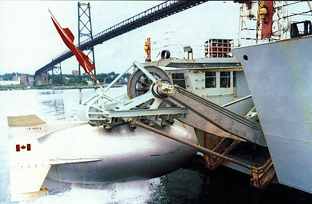
SQS-510 towfish and launching gear. Note the faired cable that would lower the towfish to depth.


The VDS launching gear was installed in a cut-out in the transom. The operator worked behind the windows on the port side of the well, and the two ports on the starboard side are for the Nixie torpedo decoy.
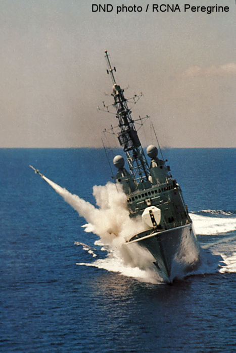
The launching derrick would lift the towfish off its cradle, andpivot out over the sternto lower the towfish into the water. The towfish would be lowered to an appropriate depth via a faired cable, and would provide better detection abilities than the hull-mounted sonar as it would be not be affected by hull noise, and could be lowered below thermal layers that might mask the presence of a submarine.


Towfish being launched. Image courtesy of Corvus Publishing Group.
VDS was a Canadian Development in the 1950s, and was adopted by several other navies before being supplanted by towed array sonar systems such as the SQR-19 / CANTASS towed array sonar fitted to the HALIFAX class. The VDS was removed from the IROQUOIS class sometime in the first decade after 2000.


VDS towfish cradle after removal of the VDS.
Once a submarine had been detected by sonar, Mk.46 lightweight torpedoes could be deployed against it from either the ship itself or a Sea King helicopter.

Starboard Mk.32 triple torpedo launcher.
Unlike the fixed double Mk.32 launchers that fire at 45 degrees out the forward corners of the helicopter hangar on HALIFAX class frigates, the triple Mk.32 launcher on the destroyers was trainable and had to be directed out over the side. It is shown here in the stored position. Compressed air would be used to force the torpedo out of the tube and into the water, from where it would deploy its own motor and hunt for a target.

Air droppable Mk.46 lightweight torpedo. A parachute is fitted in the cowling over the propeller nozzle.
The Mk.46 torpedo could also be carried by a Sea King helicopter, and air dropped with the help of a parachute that would detach when the torpedo hit the surface. These lightweight torpedoes are much smaller than the heavyweight ones carried by submarines.

Air Warfare:
Originally fitted for point-defence against aerial threats, the IROQUOIS class was refitted under TRUMP with area air defence systems that could extend an umbrella of protection to other ships operating in a task group, or to defend a convoy. First, all the radars were upgraded as part of that refit. (I have also written a summary ofradarsandfire controlsystem used by the RCN over the years).

The main mast is bristling with sensors and other antennas.
Antennas for all of the primary air warfare sensors can be seen in the photo above. Looking from bottom to top, there is the port WM-25 Separate Target Illumination Radar (STIR), the LW-08 (AN/SPQ-502) long range air search radar, two navigation radars, and then the DA-08 (AN/SPQ 501) air/surface search radar antenna on the top of the main lattice mast.
 

Port WM 25 STIR, with LW-08 in the background.
IROQUOIS carries two STIRs, port and starboard over the bridge. These would track and designate or "paint" targets for the ship's weapons systems, after being detected by the ship's other air defence radars. All the radars are gimbal-mounted to allow them to maintain a level disposition while at sea.

LW-08 long range air search radar
The LW-08 and DA-08 are the primary air defence radars, the former optimized for the long range detection of aerial targets, and the latter mounted higher on the main mast to provide better over-the-horizon aerial and surface detection. I believe the bar piggy-backed on top of each antenna dish is an Identification Friend or Foe (IFF) device.

DA 08 air/surface search radar.
The primary air defence weapon is the Standard SM-2MR missile, deployed via a 29-cell Mk.41 vertical launch system (VLS).

Mk.41 VLS.
Each cell of the 29-cell launcher can fit one SM-2 missile, or four RIM-162 Evolved Sea Sparrow Missiles (ESSM) in a quad-pack. Although the ESSM has now been added to the HALIFAX class ships in their Mk.48 VLS, I do not know if the IROQUOIS class has ever carried them. The launcher actually has room for 32 cells, but three cells are taken up by a strike-down crane (third row in, on the right of the photo above). This crane is apparently never used, and has been removed from later launchers in favour of three additional cells. In way of comparison, a USN BURKE class destroyer carries up to 3 of these launchers.

As an aside, the only vertical launched Sea Sparrow missiles that I am aware of ever being deployed from an IROQUOIS class ship was the 1981 testing of the Mk.48 VLS from HMCS HURON. I have seen a photo somewhere, as I recall showing two Mk.48 cells fixed to the side of the old Sea Sparrow launcher used by these ships pre-TRUMP.
Secondary air warfare defence is provided by both the OTO Melara 76mm gun, and the 20mm Phalanx Close-In Weapons System (CIWS). (Another version of this acronym that I have seen reads "Christ, It Won't Shoot").

Phalanx CIWS.
The Phalanx is a self-contained unit combining a 20mm gatling gun with a radar system, and is easily bolted onto ships that weren't necessarily designed to carry them. They are intended as a last ditch weapon to try and stop missiles ("leakers") missed by the primary missile system. The RCN retrofitted its Phalanx systems to the Block 1B standard, complete with the camera mounted on the side of the radome to help provide anti-surface capability.
IROQUOIS also carries four Plessey Shield flare and chaff launchers just aft of the bridge, and was also retrofitted with the Australian Nulka active missile decoy system.


Nulka launcher on the quarterdeck of ATHABASKAN in 2010.

Port Nulka launcher aft of the bridge of ATHABASKAN in 2010.
IROQUOIS can carry up to four Nulka launch cannisters, two port and starboard behind the bridge, and two side-by-side on the quarterdeck just aft of the helicopter deck. Nulka launches as a rocket from the cannister, but then can hover away from the ship and attempt to draw incoming missiles away from the ship. I was under the impression that the RCN did not buy enough units to fully equip all ships of the class, and would trade them off between the ships (on the East Coast at least).

Surface warfare:

Lacking dedicated anti-surface missiles like Harpoon (although I believe the SM-2 missile can be used against a surface target in a pinch), IROQUOIS relies primarily upon her 76mm gun and Phalanx CIWS (supplemented by .50 calibre machine guns for small surface craft). A summary of other gun systems used by the RCN over the years can be found here.
 

OTO Melara 76mm Super Rapid gun.
The Super Rapid version of the gun can fire 120 rounds per minute, and is improved over previous mountings to help counter anti-ship missiles as well as surface targets. The gun has a dedicated fire control system in the Lightweight Radar/Optronic Director (LIROD).


LIROD.
The LIROD is mounted between, and slightly forward of, the two STIRs.

This concludes, at least for now, my photo tours of IROQUOIS. I finish writing this just in time on April 25, 2015, less than one week before IROQUOIS pays off on May 1, after which 43 years of being "Relentless in Chase" will come to an end.
 
To finish up the interior of HMCS IROQUOIS, this post will cover the helicopter hangar.
The Royal Canadian Navy pioneered the operation of large helicopters from frigates and destroyers in the 1960s with the refit of the ST. LAURENT class to include a hangar and flight deck for the then-new CH-124 Sea King, followed by the commissioning of the purpose-built follow on ships ANNAPOLIS and NIPIGON. IROQUOIS and her sisters went one better, by incorporating a dual hangar to carry not one, but two, Sea Kings.


Starboard hangar looking aft, with hangar door in the background.
The three tracks on the deck in the photo above are for the Helicopter Hauldown and Rapid Securing Device (HHRSD, otherwise known as the "Beartrap").Wikipediahas a great entry on this piece of Canadian technology, so I won't go into great detail, other than to say that this device travels in these tracks and traverses the Sea King back and forth from the landing deck to the hangar. The two objects at the bottom right of the image are the refueling bells, used to accept the refueling hose from a tanker while Replenishing At Sea (RAS). Normally they are mounted at main deck level outside, between the forward superstructure and the hangar, but had been removed prior to my tour. Firefighting gear is laid out to the left, along the starboard side.


Looking forward and to port in the starboard hangar.
Easily the largest open area on the ship, the hangar wouldn't have been quite so roomy with a couple of Sea Kings embarked. In later years, only one Sea King was ever carried at one time (to the best of my knowledge), and in this photo the exercise equipment that is squatting in the port hangar can be seen. The divider between the two hangars up forward is actually trunking from the generators in the Auxiliary Machinery Room (AMR) leading up to the funnel. I believe the ammunition magazine for the Phalanx CIWS is also up there somewhere. In ALGONQUIN, it was the hangar wall to the left of the image that wasshredded by the bow of HMCS PROTECTEURas if it was a can opener, necessitating an estimated $13M in repairs (which were not carried out, leading to her premature retirement from service).


76mm gun ammunition hoist.
For one final miscellaneous interior photo, above is the view into the compartment that houses the ammunition hoist for the 76mm gun. The hoist itself is self-contained within the green cylinder, unlike the previous generation of guns, where the hoist cylinder was much bigger and could be easily entered by the crew.
That is the last of the interior photos that I will be sharing (for now at least) of HMCS IROQUOIS, and I will move to some exterior photos and then probably a tour of HMCS PRESERVER in subsequent posts. My thanks to the Navy and the crew of IROQUOIS that made these posts possible prior to her being paid off.

f the bridge of a ship is considered its brain, then warships could be considered somewhat schizophrenic: IROQUOIS has both a bridge, from where the ship is directed during normal operations, and also an Ops room, from where the ship is fought and all the combat sensors and weapons are directed. In IROQUOIS, I didn't manage to photograph the latter compartment (though I did on TORONTO, to be featured in a future posting), but I did manage to tour the bridge.
Having never served in the Navy, my descriptions of the bridge will be somewhat limited. Any feedback I receive will be added in due course.

View from the bridge, overlooking the 76mm gun and foc'st'le.
The bridge is located high on the forward end of the main superstructure, and overlooks both the 76mm gun and the 29-cell Mk.41 vertical launch system on the foc'st'le (hidden behind the gun shield in the photo above). It provides good visibility looking forward, port and starboard, and limited visibility aft (blocked by the funnel and hangar).

CO's chair looking to port.
The CO sits up front on the port side, with a SHINCOM (Ship Integrated Communications) panel to the CO's right. The flat panel TV in front of the CO's chair will have been a relatively recent addition.

CO's chair looking port and aft.
Immediately behind the CO's chair is a communications station that accommodates three SHINCOM panels.

Bridge communications station.
The three SHINCOM panels are located side-by-side running port to starboard, and appear to be operated by two personnel based on the number of chairs present. There is some sort of sonar control box mounted near the top left of the image - I am told this is for the underwater telephone for communicating with submerged submarines (presumably theAN/WQC-2 "Gertrude"or a more modern version).

Aft again from the communications station is a chair for a flag officer, on those occasions when one is embarked.

Flag officer's chair looking forward and to starboard.

I'm not sure what allowances were present in the original IROQUOIS class configuration, but the final TRUMPed configuration is intended to accommodate a flag officer and task group command staff, and the bridge has a chair for the flag officer. The flag officer's chair received its own SHINCOM panel to the left of the chair. The bridge communications station can be seen to the left (forward of which is the CO's chair), and the helm station can be seen in the centre background of the image.
 

Bridge helm station looking to starboard.

Bridge helm station: helm is on the left, throttle station on the right.
I have covered the ship's helm and steering in aprevious post, so I won't cover it in detail here. However, I will comment on the photo immediately above - in that previous post, I had indicated I didn't have a better photo of the helm and throttle stations, but then I found this photo, so I will have to update the previous post. The throttle station on the bridge is one of four in the ship, and provides direct throttle control for the two main and two cruise gas turbines in the engine room. The screen at this station will provide some of the machinery control system (MCS) readouts available in the MCR.

Forward bridge, starboard side, looking to port.
On the starboard side of the bridge there is a radar display (not sure which radar it is associated with, though I assume the navigation sets), and above there is a status panel for a variety of things such as: man overboard, fire, gyros, and the variable depth sonar (VDS) which was removed from all ships of this class several years ago.

Raytheon radar display and SHINCOM panel (to the left).
Above is a close-up of the Raytheon radar display. I assume this is for one of the navigation radars, or perhaps can display output from more than one of the ship's radars.

Looking to port from the starboard side.
Aft of the radar display is a chart table.

On the bridge centreline is a station for coordinating helicopter operations.
Between the Raytheon radar display and the CO's chair is a station for coordinating helicopter launch and recovery operations. The dials at the top right indicate wind speed and direction, the box with the red display provides ship's speed, and the grey box in the middle between the windows has switches with labels such as "Launch", "Recover", "helo AIRBOURNE", and "helo ONBOARD". To the left of that is a smaller box for controlling the window wipers. I wonder if this was the original location of the helm and throttle stations before the TRUMP refit.

AN/SPA-25F PP remote indicator (radar display).
Almost immediately aft of the helo operations station in the previous photo is this radar display. The AN/SPA-25F is a Range-Azimuth Indicator has a 10-inch screen "...designed for any standard Navy search radar system..." and can accept inputs from up to seven radar installations. To the left of the display unit is a selector switch for the LW-08 (long range air search), DA-08 (air/surface search), and Mk.127E (Sperry navigation set, of which there are two) radars. The glare shield on the display is optional, and may allow its use during night operations, or perhaps is required during the bright of day.

On the back bulkhead on the centreline is this desk. The SHINCOM panel is labelled "BOSNMATE".
When they first arrived on the scene in the early 1970s, the bridge on the IROQUOIS class must have seemed like heaven compared to the bridges of the previous class of destroyers. Instead of a cramped bridge with only voice communication with the wheelhouse several decks below, and communication with the engine room via telegraph, these ships came on the scene with not only direct helm and throttle control, but also room for multiple radar displays and other items. While large well-equipped warship bridges are very common these days, this would have been fairly rare in the early 1970s, especially for the previous steam powered generation of destroyers in various navies.
 

Looking forward and to starboard across the bridge.
Although the layout has changed, the large bridge and general concepts were also carried over to the HALIFAX class frigates 20 years later.

Your comments Please

@SpArK @Windjammer @AUSTERLITZ @Zarvan @C130
@Abingdonboy @sancho @jaunty @Srinivas @gslv mk3 @DRAY
@Dash @MohitV @Skull and Bones @acetophenol @IND151 @HariPrasad @he-man
@Prechko @vostok @GURU DUTT @janon @ExtraOdinary @RoYaL~GuJJaR @Stephen Cohen @Penguin

Having shown photos of many of the primary machinery systems throughout the ship over the last few weeks, I will finally cover the Machinery Control Room (MCR) that I have mentioned frequently in those posts. Located above the engine room (or Main Machinery Room - MMR), the MCR is the nerve centre that controls all primary mechanical and electrical systems on board the ship.
Among other things, the MCR houses 3 multi-function display (MFD) and control positions, the main electrical switchboard and electrical control panel, auxiliary helm position, and HQ1 which is the primary damage control headquarters.
It should be noted that, though I have received help from more informed individuals, some of the details I provide below will be educated (and possibly non-educated) guesses as to the purpose of the various positions and pieces of equipment, so corrections and comments are welcome. Errors are my own.

Looking forward at the three multi-function display and control positions.
I presume the three multi-function stations can be configured to control various functions of the ship, everything from water, fuel, and ventilation systems to fire pumps and mains, low and high pressure air systems, and equipment alarms. The forward position (3 MFDs) is the Machinery Control Console (MCC) where the MCC Operator sits, the middle position is called the Supervisor's Console (SC), and the after MFD is the Maintainer's Panel (MP) which is dedicated to maintenance functions (it was setup to monitor the low and high pressure air systems on board ship during my tour). The forward positions (MCC and SC) include propulsion controls, while the MP does not.

In total, there are four positions in the ship that provide propulsion control: the Bridge Console (BC) adjacent to the helm station, the MCC and SC positions in the MCR, and the Local Operator's Panel (LOP) located in the engine room between the two main turbines (see my previous post on the ship's propulsion systems).
The SHINCOM (Ship Integrated Communications) panel to the bottom left of the photo is labelled as for the main switchboard operator, the electrician of the watch. This is part of theSHINCOM 2100system developed by Canadian firm DRS Technologies in cooperation with the RCN, and has been used by several other Navies including the US Navy. SHINCOM panels can be found throughout the ship, and there are at least three in this photo (including the MCC and SC panels seen in the background of the photo if you know where to look). In the IROQUOIS class, there is a ship's telephone system that is used for most communication within the ship, and SHINCOM is used for specialized tasks only. SHINCOM was introduced during the TRUMP refit.

MCR Operator (left) and MCR Supervisor (right) positions at the forward end of the MCR.
In the photo above, the SC MFD is currently displaying the status of the fire pumps and mains.

MCC Operator position.
In the photo above, the left MFD is set to an alarms overview, with the middle and right MFDs currently blank. The main and cruise propulsion turbines would typically be started and controlled from this position, though I was told that the LOP in the engine room is typically manned as a backup when the engines are started.

The Electrician of the Watch's position.
The Electrician of the Watch sits in front of the Electrical Control Panel, from where the ship's power is regulated: from shore (if alongside) and the four generators (three Solar Saturn gas turbine generators (#1 through #3), and one diesel generator (#4)). To the right is the main electrical switchboard (400 Hz and 26V DC panels), and to the far back right of the photo is the MCC Operator position.

Electrical Control Panel.
The electrical control panel provides control over the four generators on board the ship, as well as the synchronizing of the phasing of the power from each generator. The panel to the left of the photo houses the breakers for the aft electrical buses.

The starboard & aft end of the MCR space is called HQ1, which is the damage control (DC) headquarters. This is where all damage control measures within the ship would be directed from in the event of accidental or combat damage, although there are also some redundant DC spaces within the ship.


Damage Control looking starboard and aft.
The three panels along the back wall, from left to right, are the Smoke Evac panel, the Liquid Level Management System (LLMS), and the Fire Detection, Suppression, and Control (FDSAC) panel. The latter is an automated alarm panel, where warning light buttons are superimposed on deck plans of the ship. If an alarm sensor (e.g. a smoke sensor) goes off somewhere in the ship, the associated button will light up and presumably make an audible alarm. The button can be pressed to silence the alarm. The LLMS is an inventory of various fuel (diesel for the turbines and JP5 for the helicopters) and domestic water tanks aboard ship, with gauges for each tank, and it is divided up into port/starboard and fore/aft tankage.


Damage control looking port and aft.
In the photo above, the FDSAC is now at the left of the image, and a dry erase board with ship deck plans is in the centre. The auxiliary helm station, which I did not get photos of, can be seen peaking out from behind the bulkhead to the right of the image. This helm station is similar in appearance to the one on the bridge, but "...with way less buttons...".

The MCR was a new concept to Canadian warships, as I believe no such space existed on the previous generation of destroyers. All machinery controls in theST. LAURENTderived ships were located in close proximity to the equipment they were associated with, and indeed, those controls remain on IROQUOIS to a certain extent to provide redundancy in the event that the MCR is incapacitated or cut off. Indeed, the necessity for redundancy in these controls was reinforced during theHMCS KOOTENAY gearbox explosionof 1969, where the ship continued to race along at full power because the crew was unable to immediately cut of the flow of steam to the main engines as there was no remote method of doing so, and the engine room itself was engulfed in smoke and flame.

When originally built in the early 1970s, the machinery controls provided in the MCR were state of the art. Obsolete by the time of the TRUMP refits of the early 1990s, most of the equipment in this space was replaced with new digital equipment such as the MFD positions (though I suspect the Electrical Control Panel and Main Switchboard are more or less original, at least in appearance). As the ship's are paid off (with only ATHABASKAN left in active service at the time this post is written), the equipment is once again obsolete. In an interesting comparison to the HALIFAX class frigates, which are currently undergoing their own mid-life refits, their once state of the art MCR equipment is similarly being removed and replaced with the latest and greatest, which should get them through the next 20 years. I will cover HMCS TORONTO's original MCR room in a later blog post.
 
Having covered, in previous blog posts, the propulsion and power generation of the ship, I thought I would now cover the very basics of steering the ship. Starting with the primary helm station on the bridge:

Bridge helm station.
The bridge helm station is located towards the aft of the bridge (not including the flag officer area). It includes not only the wheel (which looks like it belongs to an aircraft, and not a ship), but also an array of buttons and switches (some of which appear to control the ship's gyro navigation). As noted below, there are two steering motors, and the switches and indicator lights appear to control and show the health of separate port and starboard units. There is only one rudder. The helm station provides input to the electronic steering system, and there are several ways of operating this system. The wheel can be used, as can some of the switches on the black panel to the left of the wheel, to control the rudder.

The original steering gear setup is described in the original movie "Sisters of the Space Age" on YouTube (0:47 of Part 2).


Helm and throttle positions on the bridge.
As well, the separate position to the right provides direct throttle control for the engines. This is one of four locations onboard the ship that can directly control the two main and two cruise gas turbines, and presumably the display screen has access to the appropriate parts of the machinery control system (MCS). The helm station shown in the YouTube video indicates that the original helm station was also set up in this location (though the station itself has been updated and replaced, and relocated aft from a position near the forward bridge windows).

This is a different setup than the previous generation of RCN destroyers, which did not have direct helm and throttle control on the bridge, but rather relied on a telegraph to the engine room for throttle settings and the helm station was several decks below the bridge, with the helmsman relying on instructions from the bridge.
The ship's wheel controls the steering hydraulics, located in the tiller flats (ahem....Steering Gear Compartment).

Steering hydraulics in the Steering Gear Compartment.
The rudder is turned via a double-headed hydraulic steering ram that is connected to two separate steering motors which in turn are controlled by the ship's helm. Linear motion from the hydraulic ram is turned into rotary motion via a rapsom slide mechanism. In the background of this image, looking aft and starboard, is one of two auxiliary helm stations (the other being in the MCR).

Auxiliary helm station in the Steering Gear Compartment.
At the top of the photo is a compass repeater, so that the auxiliary helmsman can steer a course based on instructions from elsewhere in the ship. The ship only has one rudder, but there are two steering motors, and there is one steering station for each motor. There is a second auxiliary helm position, similar to the one on the bridge "...but with way less buttons...", in the Machinery Control Room (MCR). Unfortunately, I did not get a photo of this station.

Rudder post in the Steering Gear Compartment.
The rudder post protrudes up into the Steering Gear Compartment, as seen above.

The grease covered rudder post in the Steering Gear Compartment. The indicators showing port and starboard steering angles is visible towards the bottom of the image.
The destroyers, as with the frigates that followed them roughly 20 years later, are steered by a single large rudder:

IROQUOIS' rudder. Not the greatest photo, sorry.
The ship's rudder is located right aft on the hull, and just behind (and between) the ship's twin propellers. In the event that the single rudder is disabled, the ship might still retain limited maneuverability via the twin propellers, but this would presumably only be useful at sea with lots of room to spare, and would be of limited use if the rudder were jammed hard over. I'm told that steering by the main engines via the twin shafts is very effective when the ship is stopped.

Note:Input from crew members has been incorporated to update my original post. For instance, a previous version of this post indicated that I was unsure if there was still an auxiliary helm position in the MCR, as I did not take photos of it - it was confirmed to me that this exists in the MCR. Other errors have also been corrected since this was first posted.
 

IROQUOIS alongside in HMC Dockyard this morning.
Halifax Shipping Newsis reporting that HMCS IROQUOIS (DDG 280) will be officially paid off in a ceremony on the afternoon of May 1. She is already listed as "Retired" on the Navy's website, and her impending paying off was announced last year after her hull was discovered to be suffering from cracking and corrosion brought on by pounding around on the North Atlantic for more than 40 years. She was deployed at the time, and as I recall, was inspected in Boston to determine the extent of the cracking before returning to Halifax. I don't think she has been underway under her own power since her return.


IROQUOIS launching a NATO Sea Sparrow missile from her original missile launcher. DND photo, courtesy of RCNA Peregrine.
Laid down in 1969, launched in 1970, and commissioned in 1972, IROQUOIS was the lead ship of theIROQUOIS class of ASW destroyers, and was originally designated as a DDH denoting a helicopter carrying destroyer. In the photo above, her original appearance is dominated by the 5"/54 OTO Melara gun on foc'st'le and the large globes of the two Signaal WM-22 fire control directors above her bridge. Her armament was rounded out by NATO Sea Sparrow anti-aircraft missiles launched from a one-of-a-kind launcher in a deckhouse ahead of the bridge, two Mk.32 triple torpedo launchers for Mk.46 ASW torpedoes, and a 3-barreled Limbo ASW mortar in a well immediately behind the flight deck. She could also carry two CH-124 Sea King helicopters in side-by-side hangar bays to augment her ASW capabilities.


IROQUOIS departing Halifax Harbour, as seen from Chebucto Head.
Along with the rest of her class, she was refitted in the early to mid-1990s as anarea air defence destroyer. The 5" gun was replaced by a 29 cell Mk.41 vertical launch system for Standard SM-2MR anti-aircraft missiles, and a smaller 76mm OTO-Melara gun was installed on top of a deckhouse in the location of the earlier Sea Sparrow launcher. The Limbo was removed, and various sensors and equipment were replaced, greatly altering their appearance. Somewhere along the line her designation was changed from DDH to DDG, although it was my impression that even the Navy continued to refer to them by the DDH designation for some time after the refits.


IROQUOIS passing the light on George's Island.
Her paying off after 42 years of active service leaves the Canadian Navy without area air defence capability, as the Evolved Sea Sparrow Missiles (ESSM) currently carried by the modernized HALIFAX class frigates, while capable, are unable to provide the same kind of umbrella protection of an area air defence weapon. This capability will not be replaced until (and if) the promised replacements arrive as part of the National Shipbuilding Strategy sometime in the 2020s. Fortunately, the modernized HALIFAX class at least has been refitted with command and control facilities to emulate those found in the destroyers.

Of this class, only ATHABASKAN remains in service.

I will end this post with some more of my favourite photos of IROQUOIS from years past.


IROQUOIS leads VILLE DE QUEBEC and HALIFAX into a sunrise in November 2013. Perhaps it would have been more appropriate to be a sunset, but you can't have everything.

IROQUOIS passing the light on McNab's Island at dawn.

IROQUOIS launches her Sea King on her return from a NATO deployment in 2006.

Also a sunrise, darn it!
 
Warships have large electrical power requirements, in order to run everything from heating and the lights, to galley equipment, electric fire pumps, sensors, and weapons systems. On IROQUOIS class destroyers, the Auxiliary Machinery Room (AMR) houses two 750 kW Solar Saturn gas turbine generators and one 1000 kW diesel generator to provide this power. A third 750 kW Solar Saturn is located forward of the bridge at deck level, in the port side of the deckhouse that formerly housed the Sea Sparrow launcher pre-TRUMP. If truth be told, I managed to get myself completely turned around in the AMR, and didn't take enough video and wide shots to help properly orient myself in the photos that follow, so some of my typical directional commentary will be lacking in this post. I didn't get a clear picture in my head of where each piece of machinery is located.


Looking down into the lower level of the AMR. Port propeller shaft at left of ladder. The AMR is a very crowded space that houses a variety of equipment, not just the generators.
In the 1960s when the IROQUOIS class was designed, gas turbines provided the best "bang for the buck" in terms of high power from a compact package, so the Solar Saturns are the primary power source. As with the propulsion engines, all the generators are housed within skin-tight enclosures that serve to insulate the surrounding space from noise and, in extreme events, fire. They are also generally shock mounted, but I have no specific details regarding this.


The Solar Saturn gas turbine generator in the main engine room with the cover rolled back.
The two Solars in the AMR are located port and starboard on the upper level of this space. During the time of my tour, two of the three Solar Saturns onboard had been dismantled and transferred from IROQUOIS to ATHABASKAN for spare parts on the latter ship. ATHABASKAN is the last remaining IROQUOIS class destroyer remaining in active service, and was on deployment at the time of this tour.


No.2 Solar Saturn gas turbine generator, looking forward in the AMR.
Possibly to hedge their bets, a diesel generator was also included (originally a 500 kW Fairbanks Morse opposed piston engine, replaced during TRUMP by a 1000 kW Detroit Diesel). It is installed at the forward end of the AMR's lower level, between the two propeller shafts. The local control switchboard for this generator was retrofitted during the TRUMP refit, to accommodate the larger 1000 kW generator.


The diesel generator sits inside this enclosure, the interior of which doesn't appear quite as easy to access as the rolling enclosures for the Solars.

1000 kW diesel generator inside its enclosure through an open port.

Local control switchboard for the diesel generator. Built in 1987, this would have been a retrofit during the TRUMP refit.
All the electrical power on the ship is routed through the main switchgear, which is located elsewhere in the ship.


Main switchgear compartment.
As with the propulsion gas turbines, all the generating equipment is controlled remotely in the Machinery Control Room (MCR) which I will cover in a subsequent post on this blog.
Correction: Previous versions of this post were mistaken in the location of all three Solar Saturn generators. In fact, only two are located in the AMR (upper level), and the third is located at deck level in the deckhouse forward of the bridge. Many thanks to members of various Facebook groups for setting me straight.
 
Following on from my earlier post with a tour of IROQUOIS' engine room, this post will trace the path of the propeller shaft after it leaves the gearbox. After departing the gearboxes, each propeller shaft passes through a thrust block (which transfers the thrust of the propeller to the hull) and several plummer blocks (which support the shaft along its length).


Looking down into the AMR. A yellow and black propeller shaft runs down the left side of the photo.
Immediately aft of the main engine room, where the propulsion machinery is located, is the Auxiliary Machinery Room (AMR). The AMR houses three Solar Saturn 750 kW gas turbine generators plus one 1000 kW diesel generator, as well as numerous other pieces of smaller equipment. The port and starboard propeller shafts also pass through the AMR.


A propeller shaft (painted yellow & black) runs through the AMR heading aft (e.g. to the right).


Plummer blocks support the propeller shaft at the aft end of the AMR.
Due to the shape of the hull and there being two of them, the shafts must pass through not only the AMR, but also a DFO service tank, and finally the Gland Compartment before passing through the hull.


Starboard propeller shaft running through the Gland Compartment. I believe the blue hose is a hydraulic hose from the hydraulic pump for the CP props.

CP prop hydraulic pump unit.
Modern warships, including the IROQUOIS and HALIFAX classes, often use variable-pitch or controllable-pitch (CP) propellers, where the blades of the propeller can be rotated to different pitches. This is necessary because gas turbines can not be run backwards, and otherwise it might be necessary to include an extra "reverse" turbine on each shaft as was done with steam powerplants in the previous generation of warships. The CP prop allows the gas turbines to run in the same direction at all times, and the transition between forward and astern power is handled by the pitch of the propeller blades. The hydraulic pump that controls the pitch of the propeller blades is located in the Gland Compartment, two compartments aft of the AMR.


The starboard shaft passes through seals and exits the hull in the Gland Compartment.

The other side - the port shaft exits the hull.

Port propeller shaft intermediate support strut.
 

Port variable (or controllable) pitch propeller. A V-shaped strut supports the shaft just ahead of the propeller.


Starboard "running gear": the propeller shaft showing both intermediate and V-shaped support struts.
The original variable pitch propellers fitted to IROQUOIS and her sisters were only four bladed and were shaped differently (as I recall), and new propellers (presumably quieter and more efficient) were retrofitted at some point, possibly during her TRUMP refit in the early 1990s.

Update: The port variable pitch propeller, removed from HURON before she was sunk, is on display at theNaval Museum of Albertain Calgary.
 
The heart of HMCS IROQUOIS: her engine room is home to four propulsion gas turbines, producing between 12,788 shaft horsepower (cruise) and 51,000 shaft horsepower (main), along with various other equipment.

The port main (boost) turbine enclosure (left) and the local controls for all propulsion gas turbines (right, see below for better photo). I never did figure out what the Tabasco sauce was for.

The starboard Allison cruise turbine within its enclosure. The compressor stages are to the left, while the turbine is to the right.
The propulsion gas turbines are mounted backwards (compared to an airplane), with the compressor intakes pointed aft (left in the photo) and the turbine and exhaust pointed toward the bow (to the right). The shaft to the gearbox comes off the compressor end of the engine.

Starboard cruise turbine enclosure with insulation on the exhaust seen at the forward end.

Looking aft at the exhaust ducting from the starboard cruise turbine.


The starboard MAAG gearbox. Each of the green inspection ports covers a transparent window displaying part of the gearbox interior.
Each gearbox accepts two shafts on the forward end - one from each of the cruise and boost turbines.

The aft end of the starboard gearbox (to the right of the photo) connects to the starboard propeller shaft, which I will cover in a subsequent post.


Port gearbox. Note that the inspection ports are painted red (port) and green (starboard) to help identify which gearbox is which.

Looking forward from behind the starboard gearbox. Protective wire mesh at the bottom of the photo is probably covering where the propeller shaft exits the gearbox.
Although all the various bits of machinery onboard IROQUOIS and her sisters are controlled from the MCR (Machinery Control Room), there are also local controls mounted in the engine room, seen here (and seen to the right of the image at the top of this post).
 

The local control panel for the four propulsion gas turbines is located between the two main (boost) gas turbines. This panel is generally manned whenever the engines are started, and can provide local control if contact with the MCR is lost.
This panel provides direct control to all four propulsion turbines, and the diagrams and layout on this panel show the basic machinery arrangement - the cruise turbines are located outboard toward the hull on the port and starboard sides, and the boost turbines are located inboard on either side of the ship's centreline. This panel allows local control of not only the gas turbines, but also the two gearboxes (the long rectangles on the lower half) as well as the equipment that controls the pitch of IROQUOIS' controllable pitch propellers.

Cruise turbines are intended to propel the ship economically, typically at speeds of up to 20 knots or so (I'm guessing, I don't have the exact figure in front of me), while the main (boost) turbines are used to propel the ship up to its published maximum speed of 29 knots and possibly beyond. The basic arrangement of the gas turbines and gearbox is very similar to theY100 steam turbine powerplantarrangement as designed for the ST. LAURENT class of destroyer escort in the 1950s, which I have written about elsewhere.
The ship's power generating equipment is located in the Auxiliary Machinery Room (AMR), immediately aft of the Engine Room.
IROQUOIS will pay off this spring, just shy of 43 years after she was commissioned into the Royal Canadian Navy.
 
The vessel, sadly unknown to many, boasts an incredibly powerful air-defense system.
 

Latest posts

Back
Top Bottom