What's new

Chengdu J-20 5th Generation Aircraft News & Discussions

But it does seem that the JAST was an inspiration(or that the JAST was also inspired in a similar fashion??)..

I think the delta platform commonality is not a justification for taking the Rafale as an inspiration..although I do see your point regarding planform shaping especially the blended fuselage and leading edge.
I would say it is a combination of inspiration and necessity. If we go back to WW II, we will find that planform wise, the majority of front line fighters were pretty much alike. How many swept wing were there? Inverted gull? The most famous were the Stuka and the Corsair. The Lightning and the Black Widow were anomalies. The Mosquito was unusual because of its material, not of anything ground breaking in terms of planform to exploit new aerodynamic principles. Same thing for bombers. Pretty much straight wings with wing mounted engines. We did have diverse airfoils but everyone had straight wings.

Not much different today despite advances in aerodynamics knowledge. If you want to do A, B, and C well you must have X, Y, and Z. The pure delta is gone with the Concorde as the last of its kind. Instead we have variations with the cropped delta the most popular. No one need to poach a complete airframe from someone else to build his own version of another's aircraft. The long straight wings have been relegated to civilian designs and long duration high altitude drones. If you want to go fast with a certain degree of maneuverability, a delta variation is a necessity.

No different on the avionics front. If you want to exploit the aerodynamic advantages of these new fandangle planforms, you must have a FBW-FLCS. My apologies to our Russian friends but the days of the hybrid mechanically commanded and electronically assisted FLCS is done for. If the US is going to hang on to the F-15 out of financial constraints, the new F-15 will be FBW-FLCS and deadlier than it is today.

China does not need a complete 1.44 or a complete Rafale to emulate either's and both's best features to create the J-20. But in doing so, the final product will end up with remarkable resemblance to both.

Which does open up a canard discussion..
leaving the saucers and the flying wings aside.. are there no other conventional stealth designs other than those following the F-22 pattern?
Put aside the B-2 for now. Your question must include the YF-23 because to a sensor specialist like meself, both aircrafts are very similar in their 'global' perspectives regarding RCS control methods and results...

f-22_yf-23.jpg


Northrop's planform was rumored -- strongly -- to be inferior in terms of CONCENTRATIONS of reflections. But Lockheed scored the contract because its planform was superior to Northrop's in terms of agility and supercruise. Both planforms induces very similar behaviors and the YF-23's produced a greater spread of diffracted signals, resulting in an inferior concentration of these signals in most aspect angles.

The YF-23's leading and trailing edges are more uniform and further apart from each other. The F-22's planform produces a concentration of diffracted signals at the hindmost aspect, the region that the USAF considered to be the least tactically significant. We can see commonality between the YF-23 and the B-2 in this area with their 'sawtooth' patterned trailing edges. the F-22 does not have this arrangement. And the YF-23 have two less diffraction generators because the canted rudders also perform the horizontal stabs' duties.

So what this means is that for any design wishing to emulate the F-22/YF-23 in terms of low radar observability, its planform arrangement most likely will exhibit very similar visual cues. But just like how the USAF placed one set of tactical demands over another that ended up with the F-22, our latest 'stealth' aspirant will face the same debates that will ended up with it having some compromises.
 
.
Yes I understand RC model is NOT the real thing, however aerodynamic speaking, it still shares many of the law of physics with the real world, because you can also build a RC 747 and they won't be as agile as a F-16, because even if it is smaller and lighter it still have to follow the law of air friction and newton.

And what do you mean stable is NOT what you are looking or in a modern air design? The ability to make quick turns and sustain high alpha is indeed extremely important in a modern air design.
Then you should have no problems explaining why is that model so stable when the real aircraft is unstable. You confused stability with aerodynamics. The F-16 is very aerodynamics but is unstable. And so was the Wright Flyer...

Wright brothers - Wikipedia, the free encyclopedia
Modern analysis by Professor Fred E. C. Culick and Henry R. Jex (in 1985) has demonstrated that the 1903 Wright Flyer was so unstable as to be almost unmanageable by anyone but the Wrights, who had trained themselves in the 1902 glider.
Virtually the entire WW I line of fighters were inherently unstable designs.
 
.
Well, at least the RC plane has some evidence base in real physics, but your opinion is just your opinion.

:rofl: :rofl: :rofl:

It's not even the same shape as the real thing. Wings are different, canards are bigger on the model, no weight, diff. power/weight ratio.

You are funny and that's also my opinion.
 
.
..
Put aside the B-2 for now. Your question must include the YF-23 because to a sensor specialist like meself, both aircrafts are very similar in their 'global' perspectives regarding RCS control methods and results...


Northrop's planform was rumored -- strongly -- to be inferior in terms of CONCENTRATIONS of reflections. But Lockheed scored the contract because its planform was superior to Northrop's in terms of agility and supercruise. Both planforms induces very similar behaviors and the YF-23's produced a greater spread of diffracted signals, resulting in an inferior concentration of these signals in most aspect angles.

The YF-23's leading and trailing edges are more uniform and further apart from each other. The F-22's planform produces a concentration of diffracted signals at the hindmost aspect, the region that the USAF considered to be the least tactically significant. We can see commonality between the YF-23 and the B-2 in this area with their 'sawtooth' patterned trailing edges. the F-22 does not have this arrangement. And the YF-23 have two less diffraction generators because the canted rudders also perform the horizontal stabs' duties.

So what this means is that for any design wishing to emulate the F-22/YF-23 in terms of low radar observability, its planform arrangement most likely will exhibit very similar visual cues. But just like how the USAF placed one set of tactical demands over another that ended up with the F-22, our latest 'stealth' aspirant will face the same debates that will ended up with it having some compromises.

So taking your cues to the planform concentrations.. The J-20 should have high levels of concentration towards the hinds of both the canards and the wing planform???

Im not exactly sure if the USAF will ever go for golden eagles(unless its the SE).. but a golden falcon is thought likely.
In that respect Im not sure what further could be done beyond the "Have glass" modification standard to a F-16.

Which brings me to an EM question regarding communication alternatives for stealth A/C.
The F-22 still uses JTIDS and even if it is upgraded to link-22 you are still using the Em spectrum to Xmt and Rcv.. which leaves the possibility of somebody being able to know you are around. I believe there was a laser or IR comm system planned but whether it made it into the design or not.. sweetman wasnt sure about it.

So if an EM wave is susceptible to detection, what other alternatives would a stealth A/C have to communicate... ??
 
.
Seriously, we're basing discussions based on models made by a nobody that obviously didn't even attempt to make the models remotely similar to the real thing?

for the record, you can make just about anything fly with enough power(and/or light enough materials)

for instance:
38389120.FlyingLawnMower.jpg

toilet-bowl.jpg


a company that does this : FlyingThingZ – Cut Up the Sky!

now try to power them with jet engines and fly it at mach 1.5 and see how stable they are

LOL. can you get a "Coffin" version of this? I would like to see one.
 
.
:rofl: :rofl: :rofl:

It's not even the same shape as the real thing. Wings are different, canards are bigger on the model, no weight, diff. power/weight ratio.

You are funny and that's also my opinion.
Here is a valuable lesson on scaling...

Scaling down aerodynamics? - Topic
As ming says, the Reynolds number has to be considered. Using a scale model doesn't scale down the Air, so, to get a correct scale effect, you have to account for the difference in viscosities compared to the scale of the model. For example, a 1/4 scale model would require 4 X the flow velocity to get the correct scale effects. 1/28th scale models would require an impossibly high airflow rate and probably would work better in water.
Hollywood special effects people are well versed in this when they have to deal with scaled down models of real items. We cannot scale down smoke, fire, and water. Under water are the various water based phenomenon like fog and mist. We cannot scale them down either.

That is why it is hilarious that anyone would bring up that J-20's scaled down models to illustrate the real aircraft's aerodynamics and agility. Air's viscosity remain the same on both the scaled down model and the real aircraft. The man obviously have never been to an RC model event. The 'pilots' of scaled down models of the F-15 have done maneuvers that pilots of the real F-15 wish they could perform.
 
.
Here is a valuable lesson on scaling...

Scaling down aerodynamics? - Topic

Hollywood special effects people are well versed in this when they have to deal with scaled down models of real items. We cannot scale down smoke, fire, and water. Under water are the various water based phenomenon like fog and mist. We cannot scale them down either.

That is why it is hilarious that anyone would bring up that J-20's scaled down models to illustrate the real aircraft's aerodynamics and agility. Air's viscosity remain the same on both the scaled down model and the real aircraft. The man obviously have never been to an RC model event. The 'pilots' of scaled down models of the F-15 have done maneuvers that pilots of the real F-15 wish they could perform.

I have a Blade 400 RC chopper.. And have been able to mimic part of this.. I dont think any actual piloted chopper can do this without tearing itself apart.
 
Last edited by a moderator:
.
So taking your cues to the planform concentrations.. The J-20 should have high levels of concentration towards the hinds of both the canards and the wing planform???

Im not exactly sure if the USAF will ever go for golden eagles(unless its the SE).. but a golden falcon is thought likely.
In that respect Im not sure what further could be done beyond the "Have glass" modification standard to a F-16.
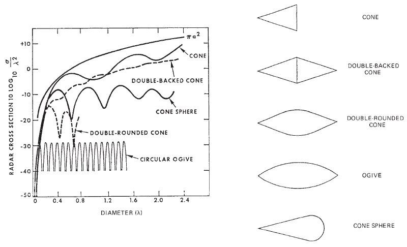
What you are asking require us to go back to the basics, which am certain is abhorrent to most people, here and on other forums elsewhere, because they usually come to these places with minds ALREADY made up. So please bear with me...

radar_rcs_simple_shapes.jpg


The top line -- the smoothest one -- represent the sphere, or the diameter of a cylinder. Our Chinese members of this forum have taken this to mean that the sphere (shape) or the curvature (surface topography) are the worst in terms of RCS production.

NOTHING can be further from the truth.

What the sphere (or diameter on a cylinder) represent is UNIFORMITY and CONSISTENCY in terms of radiation. They are usually employed as standards for measurements and calibration of just about anything involving radar.

For the illustration above, we have one thing in common for those simple shapes: Surface wave inducers. And that the RCS graphs for each shape are non-rotational with the radar signal going 'left-right', if you will.

rcs_plates.jpg


Tilt the plate enough and we will have an RCS that is far lower than the sphere when the plate will present only one edge diffraction signal: The edge facing the radar. But continuing in rotating the plate and eventually the plate will present the 'full Monty' to the radar, producing an RCS far far far greater than the sphere.

The same argument applies to all of the above shapes, not that all of them will produce an RCS greater than the sphere while under rotation, but the lesson remains: Uniformity and Consistency. In radar detection and data processing, variables and variations of any kind are natural attention attractants.

The ogive (oh-ghee-vee) may have a natural RCS lower than the sphere regardless of rotational aspect angles -- MAY because we have not touch size. But the ogive shape have three radiation modes: Surface, Specular and Edge, with four locations: two sides and two points.

Same thing with the plate except that when the plate is in 'full Monty' to the radar, there will be no surface wave behaviors whereas with the ogive, even if the ogive is completely perpendicular to the seeking radar, surface topography via curvature will induce surface wave behaviors and will deny the seeking radar some measure of detection.

For the double-rounded cone, we have three modes of radiation: Surface, Plate, and Edge. And these radiators: Two points, four plates, and two curvatures.

I will leave the other shapes as entertaining mental exercise for interested readers to figure out.

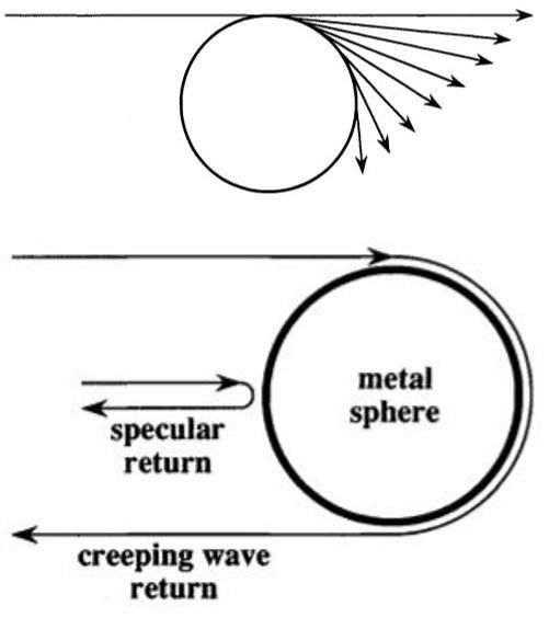
Keep in mind that the shape illustration is non-rotational. Now we will add in the '10-lambda' rule...

sphere_wave_behav_1.jpg


What the '10-lambda' (wavelength) says is that if the diameter (sphere or cylinder) is less than 10-wavelengths -- regardless of wavelengths -- then the 'creeping wave' behavior will occur. If the diameter is greater than 10-wavelengths, then the creeping wave behavior WILL NOT occur. So for the diameter (sphere or cylinder) there will be a situation where the sphere will have only one radiation mode for the seeking radar: Specular. And this is regardless of rotational aspect angles.

Now apply the '10-lambda' rule to all of the above shapes while each is under rotation.

Now amplify EVERYTHING above a million times because we are dealing with a complex body call an 'aircraft'.

An aircraft is a symmetrical but irregular body. People must understand this. Irregularity produces uncertainty which produces variations which will naturally attract attentions. This is inevitable for an aircraft whose surface topography contains rare instances of discrete of any of the above shapes but usually far worse: Combinations of those shapes.

The result is that IF our goal is to control the behaviors of these radiation patterns, we must first understand the behaviors and we started with Ufimtsev. Since we cannot avoid the plate and its accompanying edges, aka 'wings' for example, we should try to contain their numbers and avoid placing them in clusters. This led us to the next rules: Containment of radiation modes. Avoidance of radiation clusters.

Now watch the bloodbaths between the radar and aerodynamic geeks.

Nowhere am I saying that the American 'stealth' aircrafts are the ones the world should go by. What I am saying is that if a foreign power want to enter the 'stealth' arena, it would behoove said 'stealth' fighter aspirant to return to the basics, study how we did it, self examine the technological capabilities, and give it a go. But do not think that the product is beyond critical examinations by observers especially when they have at least one generation of this technology as an unofficial standard to measure all 'stealth' aspirants.

Which brings me to an EM question regarding communication alternatives for stealth A/C.
The F-22 still uses JTIDS and even if it is upgraded to link-22 you are still using the Em spectrum to Xmt and Rcv.. which leaves the possibility of somebody being able to know you are around. I believe there was a laser or IR comm system planned but whether it made it into the design or not.. sweetman wasnt sure about it.

So if an EM wave is susceptible to detection, what other alternatives would a stealth A/C have to communicate... ??
These are burst data and while they can be intercepted, the bursts are so brief that at best they could be used as an warning, not as a locator.
 
. .
These are burst data and while they can be intercepted, the bursts are so brief that at best they could be used as an warning, not as a locator.

The refresher in wave theory was appreciated.. since its been a while since I took that course.. but the object of my question was how those visual similarities between the delta platform of the J-20 and the platform of the YF-22 may allow for a certain approximation of having similar characteristics in return.

Coming to the question of bursts.. I am well aware of it since triangulation of a burst is difficult but since it does still give itself away.. Can one avoid even that?
No warning at all. yet communications continue between a stealth aircraft flight group(and no I dont mean hand signals :D)
 
.
The refresher in wave theory was appreciated.. since its been a while since I took that course.. but the object of my question was how those visual similarities between the delta platform of the J-20 and the platform of the YF-22 may allow for a certain approximation of having similar characteristics in return.

Coming to the question of bursts.. I am well aware of it since triangulation of a burst is difficult but since it does still give itself away.. Can one avoid even that?
No warning at all. yet communications continue between a stealth aircraft flight group(and no I dont mean hand signals :D)

around 1998-99 we successfully hid signal in background noise. We used wavelets and stochastic statistical algorithms to retrieve the information.

Not easy though .
 
.
The refresher in wave theory was appreciated.. since its been a while since I took that course.. but the object of my question was how those visual similarities between the delta platform of the J-20 and the platform of the YF-22 may allow for a certain approximation of having similar characteristics in return.
What I posted was for the benefits of the interested lay readers as well. But for your current question, I am going to have to tread very carefully here...

The RCS control tactic goes: Model, Predict, and Measurement.

With computer assist, 'super' or not, the 'Model' and 'Predict' are often interchanged. But 'Measurement' always have the final words: Yea or Nay (dumbass).

Based upon what we know of the above simple shapes and how they would respond, we can take a step up and model/predict how these shapes would respond in combination with each other. We have done such modeling/predicting and our measurement, which is the final step in any RCS control experiment, have bear out our modeling/predicting. As the complex body increases in complexity in terms of shape combinants to include their sizes, our modeling/predicting equally increases in complexity and of course, errors when measurements do not support our theories. Then it is back to the proverbial drawing board.
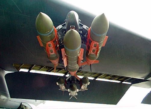
jdam_gbu30.jpg


If modeling/predicting is that easy to support by measurements, we would not be enclosing the above RCS mess, as in 'internalizing' them in some ways, fuselage or RCS controlled 'pods'. But what we also do know is that complex structures on a complex body do exhibit identifiable signal characteristics and our problem have always been discernment then extraction of those characteristics out of the background. The greater the complexity, the greater the uniqueness of those characteristics, but not necessarily in amplitude since destructive interference will deny us that factor.

A wing is a much more complex structure than the sphere or a cylinder but far less than a cluster of missiles and bombs as shown above. So have anyone in the 'stealth' arena did a study on the ranges of these signals, from the simple sphere to a cluster of cylinders and plates (missiles and bombs), to anywhere in the middle? Yes, we did. Anyone else? I do not know.

Here is where I must tread carefully and I will use PUBLICLY available sources to give you a hint of what we 'may' have in store for potential 'stealth' aspirants...

IEEE Xplore - Abstract Page
Cluster Sorting of Radar Signals Using Intra-pulse Feature

Author(s): Song Yunzhao Univ. of Electron. Sci. & Technol. of China, Chengdu
Wan Qun ; Liu Gang

Common parameters for signal description can hardly meet practical requirement of radar signal sorting and recognition. Aiming at the problem of signal sorting system, DCT (discrete cosine transform) features and BT (product of bandwidth and time width) feature are introduced to form a new description vector. DCT features not only can reflect modulation mode but also are not sensitive to noise. BT feature can reflect some parameters of modulation. Both of DCT features and BT feature are easy to get. At last, results of weighted dynamic cluster show that DCT features and BT feature are effective for sorting.
What the abstract really mean is that we are trying to extract a cluster of signals that are related to each other in some significant ways. The signals MUST relate to each other.

First...The words 'Cluster Sorting'...

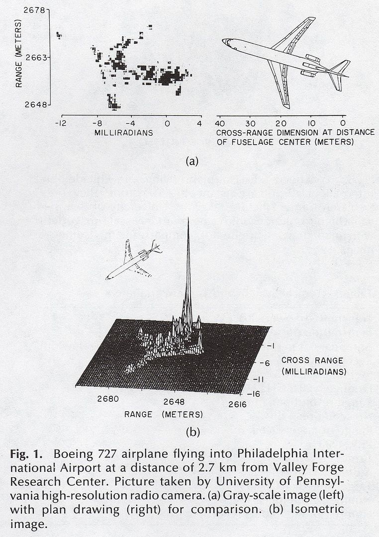
airliner_rcs_01.jpg


The above is an example of such a cluster or 'clustering' of signals and whose discrete members are related to each other by virtue of their parent -- the aircraft.

The floor represent a threshold and that is usually the 'clutter rejection threshold'. Clutter is extremely problematic in radar detection. What 'clutter' is -- Is a set of signals that matches a library of signal characteristics that we IMMEDIATELY discard. Primary in that library is amplitude. Cosmic background radiation (CBR) is a member in that library. Do we want CBR to be on our scope? No. But our astronomer pal would want to study this CBR thingie. We do not want to see birds, but our ornithologist pal does. We do not want to see hyrdometeors, but our meteorologist pal does. So what clutter really mean is that it is completely arbitrary. One man's junk is another man's treasure. The library and line that represent clutter processing depends on what one is looking for (above) and discarded signal characteristics that matches said library (below). A radar engineer can spend his entire professional career -- DECADES -- just working on clutter processing, then retire in comfort to a boathouse in Florida.

Now...The words 'Intra-pulse'...

radar_pulse_example.jpg


The above is an example of the basic characteristics of a standard radar pulse transmission. The words 'Intra-pulse' refers to the periods of 'silence' or non-transmission between each pulse.

Not the PRI. NOT.

The PRI is measured either from leading edge to leading edge or trailing edge to trailing edge. The intra-pulse period is measured from trailing edge to leading edge.

The problem for 99% of the world's radars regarding 'stealth' is that the aircraft produces a set of signal characteristics that matches the most commonly known clutter libraries that contains: birds, insects, hydrometeors, flora, and fauna. When you buy a radar system, civilian or military, these libraries are already included either by hardware via electronics engineering of interchangeable circuit boards or by software. Usually a combination of both.

The 'non-stealth' aircraft produces a cluster of signals that rises above the clutter rejection threshold, hence it is 'detected' and 'tracked'. The individuals of this cluster have one thing in common with each other: amplitude. Cluster sorting by amplitude alone is sufficient to 'detect' and 'track' this target.

The 'stealth' aircraft produces a cluster of signals that DOES NOT rises above the clutter rejection threshold, hence the entire cluster is 'discarded'. The individuals of this cluster also have one thing in common with each other: amplitude. But much much much less of it. So cluster sorting by amplitude alone is insufficient. We dare not lower the clutter rejection threshold because we would be overwhelmed by so much raw data. But if we have no choice but to lower this threshold, we must find some other ways to process the raw data based upon signal characteristics other than amplitude.

An aircraft is a complex body comprised of diverse shapes, from spheres to spheroids to plates to ovoids to cylinders to half cylinders to ogives and so on. The sharp transitions from one shape to another -- surface discontinuities -- and from one material to another -- medium discontinuities -- are what made an aircraft 'non-stealth'. A 'stealth' aircraft is still a complex body except that it has much lower incidences (events) of surface discontinuities and medium discontinuities. But if a surface discontinuity and/or a medium discontinuity must exist, and they do exist, the next goal is to deny the seeking radar the availability of the signals produced and if that denial is not possible, then reduce the intensity of that availability. Put it another way: Both the denial of availability and the reduction of intensity of what is available made an aircraft 'stealthy', based upon the clutter rejection threshold, of course.

We know from long ago that complex bodies produces different signal characteristics based upon the diverse shapes and relationships of those shapes. What the authors are putting forth is an attempt at data processing of what happens to a target with respect to the clutter rejection threshold by analyzing the target's clustering characteristics BETWEEN pulses.

Here is how...

Because the target in question is a moving target across a KNOWN background that is usually discarded as 'junk' or clutter, the target will produce a phase shift that could occur from pulse to pulse. The 'junk' or clutter' will not produce such a phase shift.

The proposed method would:

- Analyze EACH signal inside the clutter rejection threshold, from pulse to pulse,...

- Search for phase shifts from pulse to pulse,...

- Determine if these phase shifts are in a cluster,...

- Determine if the background clutter produces any phase shifts,...

- Cancelation of any non-shifting signals.

Then declare a 'target' or not. Hence the words 'Intra-pulse'. The potential for false target declaration is great because of dependencies on avionics hardware and/or software sophistication. However, IF the system is comprised of physically and spatially distinct antenna arrays technique called 'displaced phase center'...

Theory of displaced phase center antenna for space based radar applications
A theory of the displaced phase center antenna system for space based on radar applications is presented. The matching condition required to compensate for the motion of the satellite platform so that clutter cancellation can be achieved is first derived. Analytical expressions for the signal and clutter covariance matrices are given. With the aid of a simplified model, numerical values of an improvement factor are obtained. These results illustrate the dependence of the level of clutter rejection on radar parameters such as: grazing angle, pulse train duration, pulse repetition rate, and antenna aperture size.

Phased Arrays and Radars
Clutter Rejection for an Airborne System (STAP and DPCA)

To cope with ground clutter and sidelobe jamming for airborne radar, extensive work is ongoing toward the development of an airborne phased array using space-time adaptive processing (STAP).25,26 STAP is a general form of displaced phase center antenna (DPCA) processing. STAP had been demonstrated several years ago on a modified E2-C system by NRL.27,28 More recently, a flight demonstration STAP provided 52 to 69 dB of sidelobe clutter cancellation relative to the main beam clutter.29 This system used an array mounted on the side of an aircraft. The antenna had 11 degrees of freedom in azimuth and two in elevation, for a total of 22. Before STAP, the antenna RMS sidelobe level was -30 dBi; with STAP, it was –45 dBi.
...Then this potentiality is removed but currently it is not yet feasible for something small like a fighter aircraft, which does not have sufficient volume space to carry two antennas and to space them apart to take the full effect. Data processing is intensive because the system is effectively processing everything from CBR to birds to insects to flora and to fauna. The system does not lower its clutter rejection threshold, it simply uses it as a reference, so in a way, the word 'rejection' here is a bit of a misnomer. The system can even have a dynamic clutter rejection threshold capability based upon situational needs, but that would increase the data processing requirement to cover all possible tactical scenarios. So to date, only something as large like an AWACS can have this DPCA capability.

The results are extremely dramatic...

radar_dpca.jpg


Dual antennas for DPCA capability is not an option for small aircrafts. Cluster sorting via intra-pulse analysis is one of MANY techniques and is a more attractive possibility for a single antenna system but is limited to just the PRI. Keep in mind that this single antenna system is also limited in scan direction and area.

Frequency is probably the most talked about characteristic of anything related to EM discussions, particularly the phrase 'frequency hopping'. The more precise phrase is 'frequency agility'. Some radar systems are more frequency agile than others, at the expense of system hardware and cost, of course. But as we can see above with the illustration containing all the basic signal characteristics of a transmission, frequency is not the only signal characteristic in a typical radar transmission. If our system is more capable, we would have 'parameters agility', meaning the ability to manipulate -- at will -- all signal characteristics of a transmission.

For example...

radar_pulse_rep_interv_1.jpg


The typical AM radio signal is amplitude agile. The FM side is frequency agile. The above example is the lesser known PRI agile or PRI 'jittering' in electronics warfare jargon. Data analysis of complex returned signals from a PRI agile transmission is already possible. The probability of a radar system to have this capability is another issue. Now add in amplitude, frequency, bursts of continuous wave (CW), and many other combinations. Each combination have been studied (by US) to see what kind of signal a certain planform will produce.

So if we know that complex bodies will produce complex variations of signals, from phase shifts to Doppler to amplitude and so on, is it possible to have a single antenna system sophisticated and powerful enough and is equipped with a comprehensive library of clustered signals characteristics to fully exploit parameters agility to detect low radar observable aircrafts? Yes.

We ALREADY know what a 'delta wing' look like as far as complexity of returned echo goes. As long as one aircraft give us a reference signal, we can extrapolate with high confidence of precision and accuracy what a smaller or larger delta wing will look like. A canard is just another wing. It is a 'canard' by virtue of physical placement but its aerodynamics and EM characteristics are no different than the 'wing'. But because of its size and physical location on a complex body, the final set of signal characteristics will be different than that of the 'delta wing' and the fuselage. We know what this set of signal characteristics look like.

Dual antennas for DPCA capability is largely hardware based for discernment and extraction of unique clusters inside a background. Pulsed transmissions with parameter agility is another method for the same desire. You can bet your next year's salary that there are more methods than what I have presented here.

I made no claims on exact figures but based upon the visual similarities of planforms and upon what I know from my own experience, I will 'opine' :lol: that we (the US) know what each planform look like under EM bombardment and those libraries will be waiting for the next 'stealth' aspirants.

Coming to the question of bursts.. I am well aware of it since triangulation of a burst is difficult but since it does still give itself away.. Can one avoid even that?
No warning at all. yet communications continue between a stealth aircraft flight group(and no I dont mean hand signals :D)
It does give itself away, of course. But a reasonably directional communication method can further reduce the odds of detection...

f-22_cni_ew_arrays.jpg


The initials 'CNI' stands for: Communication, Navigation, and Identification.

That is what the USAF chose to disseminate to the public. Now you know why the F-22 is called 'an antenna farm'. Between each fighter, the entire system can passively monitor each friendly aircraft's position and will use only the appropriate antenna for these data transmission bursts.

Then you add in this...

around 1998-99 we successfully hid signal in background noise. We used wavelets and stochastic statistical algorithms to retrieve the information.

Not easy though .
And the odds of detection by a hostile force is reduced even further.

A flight of 4 F-22s can divide the sky into discrete areas of responsibility for each aircraft with everyone in 99% passive detection mode and communicate with each other using only physically discrete antennas.

Now multiply this capability at least twice for the F-35.
 
.
...We dare not lower the clutter rejection threshold because we would be overwhelmed by so much raw data....

is this a computer hardware issue? As in lack of processing power? To process more data and thus lower it.

The isometric image is also interesting. I'm assuming that picture isnt that new (going by the looks/print of the scan, the Boeing 727), it's made with a stationary radar at 2.7km.
Could a radar in a today's fighter draw that up in higher detail at a larger distance (some military value, lets say 60km intercept distance-or more if power allows it) in real time ?
To help the pilot identify precisely what he is up against.
 
.
is this a computer hardware issue? As in lack of processing power? To process more data and thus lower it.
Sort of 'Yes' and 'No'. Lack of processing power in terms of hardware can be compensated by having a very narrow beam, after all, a radar cannot process anything that is outside of its capture capability -- beamwidth. The downside to that is increase search time if there is a volume assigned.

The isometric image is also interesting. I'm assuming that picture isnt that new (going by the looks/print of the scan, the Boeing 727), it's made with a stationary radar at 2.7km.
Could a radar in a today's fighter draw that up in higher detail at a larger distance (some military value, lets say 60km intercept distance-or more if power allows it) in real time ?
To help the pilot identify precisely what he is up against.
Yes. But you should understand that a radar scope is nothing like that graph. I used it to illustrate the point about a cluster of radiation generators. Or 'unnatural' sources, if you will. We have radars that against stationary targets, can produce visualizations whose clarity that approaches that of a B/W photograph.
 
.
Yes. But you should understand that a radar scope is nothing like that graph. I used it to illustrate the point about a cluster of radiation generators. Or 'unnatural' sources, if you will. We have radars that against stationary targets, can produce visualizations whose clarity that approaches that of a B/W photograph.

I didnt mean radar scope.
I meant software would be taking real time raw data from the radar, and drawing it on some display in the cockpit if the pilot wanted to.

You can imagine better with a crude example:
Pilot gets intercept order, target unknown, he gets into some sort of range, points the radar in the general direction, finds it, software/radio camera snaps an image and then gets that image drawn on a display.

And yes i have seen decent detail radar images of stationary objects (buildings) and moving (asteroids) before, i was just wondering if there is any sort of military application along the lines of what i described in use. Is the image resolution big enough to allow type recognition for example.
 
.

Pakistan Defence Latest Posts

Country Latest Posts

Back
Top Bottom