What's new

T-80 and T-84 Main Battle Tanks Information pool

Manticore

RETIRED MOD
Joined
Jan 18, 2009
Messages
10,115
Reaction score
114
Country
Pakistan
Location
Pakistan
Recently I came across some work done by tanknutdave explaining the evolution of T80 and I decided to post the information here. A lot of members says that some of our t80ud have advanced features of the t84 which we can discuss later on. I will also post the link of the yugoslavian m84 due to the fact that they as well as the ukranians have helped us in manufacturing the alkhalid. Basically its just an info pool/dedicated t80 discussion thread


The Russian T-80 Series


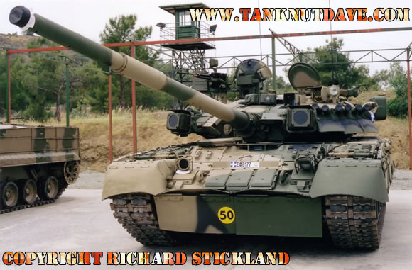
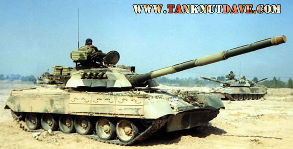
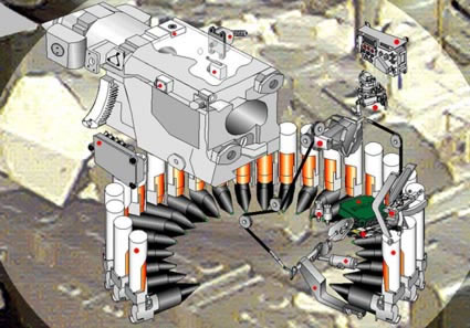
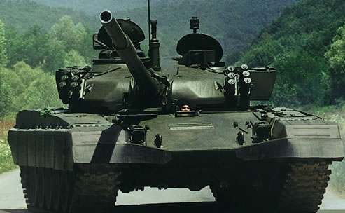
When the T-80 entered service in the former U.S.S.R in the late 1970′s, many NATO countries confused it as the T-72. It did have the same self loading carousel that reduced the crew size down to three men as used in the T-72 as well as the use of reactive armour on the turret, but mechanically it was a different tank.

The T-80 started out as an improved version of the highly successful T-64 and was designed and produced by the SKB-2 design bureau at the Kirov arm’s factory in Leningrad. One of the design improvements was the introduction of a gas turbine engine (the GTD-1000T and GTD-1000TF) and the T-80 was the first tank in the world to be fitted with one. One of the other improvements made was to the suspension system by using components from the T-72′s. The T-80 is a much smaller and lighter MBT than that of NATO countries MBT’s at the time and current one’s, weighting only 46 ton’s on average.

In 1985 the T-80 went through a major upgrade program at the SKB-2 arm’s factory in Leningrad. It received a new type of reactive armour called “Kontakt-5″ and is able to withstand modern armour-piercing fin-stabilized discarding sabot rounds. Its former secondary weapon, a remotely controlled commanders MG was replaced with a pintle-mounted one and fitted with the Brod-M deep wading equipment. The biggest change was the replacement of the old gas turbine engines, which drank fuel at an alarming rate and limited its operational distance. It was fitted with the GTD-1250 three-shaft engine, with two cascades of turbo compression producing 1250hp and with its lightweight it has earn’t the nickname as the “flying tank” and was redesignated as the T-80U.


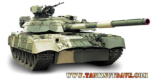
Whilst the T-80U program was happening, the Morozov Design Bureau in Ukraine was developing a diesel-powered version, designated the T-80UD (“D” for diesel). It took on all the main improvements of the T-80U with a few exceptions such as keeping the secondary weapon, the commanders MG as remotely controlled. It is also able to fire from its 125mm 2A46 smoothbore main cannon the improved wire guided 9M119 Svir missile and of course not using a gas turbine engine. Instead it was fitted with a 1000-hp 6TD-1 6-cylinder multi-fuel two-stroke turbo-piston diesel engine, which gives it a far better fuel efficiency and a longer operational range than T-80′s with turbine engines.

Between 1987 to1991, roughly 500 T-80UD tanks were built at the Ukrainian Malyshev Factory, but when the wall fell in Germany and the U.S.S.R broke up, 300 of them were still at the factory and are more commonly seen in the Ukrainian Army rather than in the Russian Army.

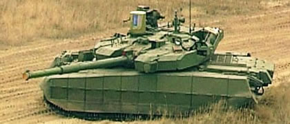
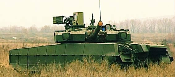
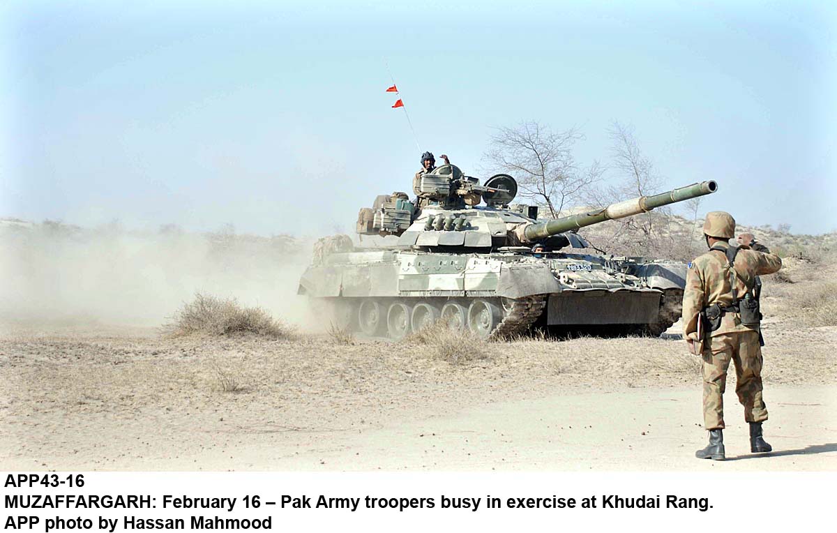
The future of the T-80U & T-80UD is turbulent. It has had many upgrades and versions built. The Russian Army are moving towards using the T-90 after the T-80′s high fuel consumption and poor combat performance in the Two Chechnya Wars. Exports of the T-80UD have been slow, mostly due to Russia not supplying The Ukraine with turrets and technology, which was resolved by the development of domestic components. As a result Pakistan ordered over 300 of them between 1997 to 1999. With the development of domestic components and independence in tank building the Ukrainians have now developed an improved version of the T-80UD, designated the T-84 for export. The T-80 series are still in service with a number of countries including: Belarus, Cyprus and Russia.

T-80: the original production model, which was only produced in very small numbers.
T-80B: was the first mass produced variant.
T-80BK: was the command variant of the T – 80B. It was equipped added communications equipment.
T-80BV: was the variant first fitted with Explosive Reactive Armour.
T-80BVK: was the command variant of the T – 80BV. It was equipped added communications equipment.
T-80U: was the variant that had the biggest overhaul. It saw changes to the secondary weapons, new engine decking, new armour, vision equipment and commanders’ equipment.
T-80UD: saw the replacement of the gas turbine engine with a diesel.
T-80UK: was the command version of the T – 80U.
T-80UE: was the same as the T – 80UK but without the command equipment. It did retain the Shtora-1 system (IR jammer to defeat guided missiles).
T-80UM: saw the replacement of the diesel engine to a new 1250hp gas turbine.
T-80UM1: has the Shtora-1 system fitted and the gas turbine beefed up.
T-80UM2: was fitted with a new cast turret.
BREM-80: is the T – 80′s armoured recovery vehicle.

t80.jpg


http://tanknutdave.com/the-russian-t-80-series/
 
Last edited by a moderator:
The Ukrainian T-80UD Main Battle Tank

Being a member of the former Soviet Union & a key industrial state, Ukraine built a number of tanks under licence during the Cold War period and one of these was the T-80. Seeing the problems the gas turbine engine caused for the Russian T-80U, the Ukraine further developed the vehicle (under the leadership of Nikolay A. Shomin) based on the Izdeliye 476 tank and the running gear of the T-80.
In 1985 production begun at the State Enterprise Malyshev Plant (now known as Kharkiv Morozov Machine Building Design Bureau AKA KMDB) of the T-80UD (though a large numbers of the components were supplied by Russia), the key difference being the replacement of the gas turbine with a diesel engine, hence the ‘D’ in its re-designation.

The new engine is the multi-fuel two-stroke turbo-piston 6TD-1 6-cylinder diesel, which generates 1000hp. It provides an increased range over the T-80U. The air inlet for the new engine allows air to be ducted from the least dusty part of the vehicle and the two parts to the air filtration system, the centrifugal pre-cleaners and the air cleaner casing, aid the vehicle in water fording to a depth of 1.8m (5m with fording equipment) and further increase its operational range in hot climates up to 1000km without the need to change filters. The top of the engine compartment is fitted with special heat insulation to reduce the heat given of by the engine, thus reducing its thermal signature.

The suspension is torsion bar which is covered with a skirt and the forward part is under ERA armour. To reduce dust kicked up by the vehicle, a large rubber matt is hung at the front of the vehicle. The vehicle has as standard, a very basic dozer blade so it can dig its self a scrape to lie up in, within 15-40 minutes depending on the type of ground. Anti-mine equipment can be installed, such as the KMT-6 plough-type system and KMT-7 roller-type system. The range of the vehicle can be extended with two additional fuel drums at the rear of the vehicle.

The vehicle uses composite armour and ERA in order to keep the weight of the vehicle down. The vehicle has a standard NBC system and fire detection/suppression system.

The main cannon is the 125mm KBA3 smoothbore cannon with a cal length of 48 and is fitted with a thermal sleeve and fume extractor. The cannon uses two-part munitions and can carry 45 rounds (APFSDS, HEAT & HE-FRAG), 28 of these are kept in the vehicles autoloader, reducing the crew to three.

The vehicle is equipped with a guided missile system. A laser guided, tandem charge, ATM can be fired from the main cannon with an effective range of 5000m. It’s reported to be able to engage hovering helicopters and concrete emplacements.
Russian tank cannons and their derivatives have a much poorer accuracy compared to Western tanks, hence the added ATM capability to increase the vehicles lethality. Some say it’s the quality of the main cannon, whilst others say the quality of the tank rounds are poor, or both.

The vehicle is able to generate its own smoke screen by injecting diesel fuel in the engine exhaust and is also equipped with a bank of four electrically operated smoke grenade launchers on either side of the turret.

For close encounters, the vehicle has a coaxial 7.62mm MG (controlled either by the commander or gunner) and a 12.7mm MG on the commanders cupola, which can be used in the anti-aircraft role. It can be elevated from -5° to +70° and traversed through +/-75° to the right and left of the vehicle longitudinal axis, or through +360° together with the turret. It can be controlled by the commander from within the vehicle, limiting his exposure to close quarter fire.


Calibre
125 mm
Type
smoothbore gun
Breech-block type
semiautomatic with horizontal placement of the wedge
Gun length
6678 mm
Barrel length
6000 mm (L48)
Normal recoil length
260 to 300 mm
Maximum possible recoil length (STOP)
310 mm
Initial pressure in the recuperator
59 to 62 kgf/cm2
Number of recoil brakes
2
Placement of recoil brakes
symmetrical relative to the gun bore axis
Number of recuperators
1
Resistance to recoil
98000 kgf
Gun weight
2500 kg
Weight of gun recoiling part
1900 kg
Muzzle velocity (when firing 3VBM17 “MANGO” armour-piercing round)
1700 m/s
Maximum acceptable calculated gas pressure in charge chamber
6500 kgf/cm2
Gas pressure in charge chamber (when firing 3VBM17 “MANGO”)
5660 kgf/cm2 (at t=15°C)
Horizontal dispersion (APDSFS and HEAT at 2000m range)
0.2 mils
Vertical dispersion (APDSFS and HEAT at 2000 m range)
0.2 mils
The vehicle has a modern computer fire control system and sighting equipment:

1V528-1 ballistic computer – uses inputs from the sensors measuring tank speed, crosswind speed, target range, and course angle, will other information has to be manually inputted such as ambient air temperature, charge temperature, barrel wear, ambient air pressure. It is also able to calculate when the high-explosive fragmentation projectile with controlled detonation should be detonated over the target. It also has fire gating capability. This means the main cannon will only fire when the misalignment between the line of sight and the gun bore axis is within pre-determined limits, after the gun firing button has been pushed. The fire gate size is adjusted when calibrating the fire control system after installing it in the tank.

Gunner’s 1G46 day sight, gunner’s TO1-KO1E night vision system – the sight is stabilised for line of sight and incorporates a laser range-finder and a missile guidance capability. For export models option, the Buran-Catherine-E thermal imaging sight can be fitted.
Commander’s PNK-4S observation and sighting system – the sight is stabilised and has three channels: a day unity vision channel, a day channel with magnification of x8 and a night channel with magnification of 5.4x.
PZU-7 anti-aircraft sight & 1ETs29 anti-aircraft machine gun mount control system – Used to control and engage the 12.7mm MG against hovering anti-tank helicopters.
The Ukrainian Army of 2005, have 271 T-80UD’s and is also in service in Russia.

t80ud.jpg
revamp.jpg
1.jpg


Pakistani T-80UD

With the collapse of the USSR, Ukraine ‘inherited’ a stock pile of 300+ T-80UD’s which were left at the Ukrainian factory. In 1996 Ukraine signed a deal to sell 320 of the vehicles to Pakistan. Some deliveries were made despite objections from Russia, who claimed the vehicle was in fact a Russian vehicle and refused to supply the Ukraine the parts to modernise the tank to the agreements promised standard. How ever the Ukraine had been developing their first tank to rely almost completely on indigenes parts, the T-84, so used parts from that vehicle to complete the production and delivery to the Pakistani Army in 1999, totalling 320 vehicles.

The following key support vehicles can also be supplied to provide the T-80UD MBT with technical and logistic support during its operational life:

armoured repair and recovery vehicle (based on the T-80UD chassis)
armoured vehicle-launched bridge (based on the T-80UD chassis)
tracked carrier with a carrying capacity of 12 t (its main sub-assemblies are similar to those of the T-80UD)
various tank maintenance mobile workshops (based on the chassis of cross-country vehicles)

The T-80UD design has now been surpassed with the T-84.

11.jpg


http://tanknutdave.com/the-ukrainian-t-80ud-main-battle-tank/
 
The Ukrainian T-84 Oplot Main Battle Tank
T-84 is Ukrainian upgrade of the T-80UD. New welded turret and Shtora-1 countermeasures suite, 1,200 hp (895 kW) 6TD-2 diesel engine.

T-84U is Ukrainian upgrade of the T-84. New armoured side skirts, turret-conformal Kontakt-5 explosive reactive armour, auxiliary power unit, thermal imaging sight, satellite navigation, commander’s laser range-finder, muzzle reference system, and other improvements.

T-84 Oplot is T-84U with new western-style turret, but retaining the 125 mm gun. The Oplot tank features a new welded turret with separate crew and ammunition compartments with blowout panels on the ammunition compartment, a new bustle-mounted autoloader. A small number are in service with the Ukrainian Army.

The BM Oplot main battle tank is a tracked fighting vehicle that features a high firepower, reliable protection and high mobility.

The tank is intended to destroy all types of ground (floating) and low-flying low-speed ait targets under the conditions when the enemy fires back.

The vehicle can fulfil a wide range of combat missions under various climatic, weather and terrain conditions in the ambient temperature range of -40 to +55 degrees Centigrade, air humidity of up to 98% at temperature of +25 degrees Centigrade, height above sea level of up to 3000 m and with ambient air dust content available in real terrain conditions

FIREPOWER
Main Gun - Model KBA-3 Calibre 125 mm
Breech – type horizontal wedge-type, semi-automatic
Elevation/depression – angles (up to rigid stops). from -4 to +15 degrees
Horizontal aiming – (together with the tank turret) 360 degrees
Elevation - 0.2 mrad (APFSDS, HEAT, R=2000 m)
Azimuth - 0.2 mrad (APFSDS, HEAT, R=2000 m)

Coaxial machine gun – Model KT-7.62 (PKT) with removing powder gas
Calibre – 7.62 mm
Technical rate of fire – 700 to 800 rpm

Anti-aircraft machine gun system
Control - remote
Control modes – 1) automatic 2) stabilised in vertical plane
Armament model – KT-12.7
Calibre – 12.7 mm
Ammunition feed – belt-type
Technical rate of fire – 700 rpm
Number of cartridges in a belt – 150
Max firing range – at air targets 2000m / at ground targets 2000 m
Firing (aiming) angles – elevation from -3 to 60 degrees / azimuth 360 degrees

LOADING SYSTEM

The loading system is a system intended to automatically load the main gun with ammunition of the available types and consisting of a conveyor, automatic loader and control system.

Type – electric hydraulic mechanical, with fixed loading angle
Number of projectile – types 4
Conveyor capacity – 28 rds
Conveyor rotation – in both directions
Conveyor rotation speed – 25-33 degrees per sec
Loading cycle durationс – minimum 7 sec (if the conveyor turns through 1 step) / maximum 12.5 sec (if the conveyor terns through 180°)
Loading cycle duration if using manual drives of the loading system – if the conveyor turns through 1 step within 1 minute / if the conveyor turns through 14 steps within 1.6 minutes

Removal of a used cartridge case stub with placing it into an empty loading tray without damaging air-tightness of the fighting compartment
Round ramming type tandem-type ramming projectile and charge together) during one cycle
Availability of back-up drives manual drives of conveyor, manual ammo feed mechanism, manual conveyor lock and manual gun lock
Conveyor replenishment time (in replenishment mode) 15-20 minutes.

Control system of the loading system installed in the tank is intended for:

Ensuring control over operation of mechanical and hydraulic units of the loading system
Ensuring control of the firing circuits of the main gun and coaxial machine gun
Storing information about the rounds placed into the loading system conveyor

INTEGRATED GUN-AND-FIRE CONTROL SYSTEM (IGFCS)

The IGFCS ensures the following:

Automatic generation, with subsequent introduction into the armament control devices, of super-elevation and lateral lead angles, with taking into account various deviations of the real firing conditions from the standard ones
Possibility for the commander to override the gunner and fire the main gun and coaxial machine gun from the commander’s station
Firing the anti-aircraft machine gun from the commander’s station accurate aiming from 0.05 to 1 degrees/sec – maximum at least 3 degrees/sec Azimuth: – minimum within 0.05 degrees/sec -accurate aiming from 0.05 to 1 degrees/sec – maximum at least 3 degrees/sec

Laser range-finder – target ranging limits 400-5000 m

Time required for preparation of the first shot of the gun - if the tank is stationary - 10-12 sec / if the tank is on the move - 10-15 sec
Gun firing range in all conditions of vehicle operation – APFSDS at least 2800m / HEAT, HE-FRAG - at least 2600 m

1G46M gunner’s sight

Type – Optical aiming device with two-axis independent stabilisation of the field of view, with laser range-finder and laser channel for missile guidance
Magnification – 2.7-12
Field of view - 4-20 degrees
Aiming angles of stabilised line of sight – elevation is -15 to +20 degrees / azimuth (8±1) degrees / together with the turret 360 degrees
Speed of aiming of the line of sight Elevation minimum within 0.05 degrees per sec / accurate aiming from 0.05 to 1 degrees per sec / maximum
at least 3 degrees per sec
Azimuth – minimum within 0.05 degrees per sec
Accurate aiming from – 0.05 to 1 degrees per sec
Maximum – at least 3 degrees per sec
Laser range-finder – target ranging limits 400-5000m

PTT-2 thermal sighting system

The system is intended to observe, detect, recognise and identify targets and to deliver aimed fire from the main and coaxial machine gun under all conditions of vehicle operation.

Type thermal – monocular (with built-in micro-monitor)
Operational spectral wave band – 8-12 micrometres
Fields of view – wide field of view 9×6.75 degrees / narrow field of view 3×2.25 degrees
Electronic magnification - 1.5×1.12 degrees
Operational ranges – Detection range (narrow field of view) at least 8000m / Recognition range (narrow field of view) at least 4500m / Identification range (narrow field of view) at least 2500 m

PNK-6 panoramic sighting system

The system is intended for:

1 – detection, recognition and identification of ground and air targets by day and at night from the tank commander’s station
2 – target ranging by means of the laser range-finder
3 – designation of targets to the gunner
4 – firing the main gun and the coaxial machine gun from the commander’s station in the override more
5 – firing the anti-aircraft machine gun
6 – Technical characteristics

Field-of-view stabilisation independent, in two axes:

Aiming angles of the stabilised line of sight – Depression at least 15 degrees / Elevation at least 60 degrees
Traverse - 360 degrees
Magnification of the day vision channel – 1.2; 6; 12
Field of view of the day vision channel – 30; 10; 5.5 degrees
Field of view of thermal channel – Wide field of view 9×6.75 degrees / Narrow field of view 3×2.25 degrees
Electronic magnification - 1.5×1.12 degrees
Spectral range of the thermal camera – 8-12 micrometres
Range of detection of a TANK-type target – Through the visual channel at least 5500m / Through the thermal channel in the narrow field of view at least 8000m
Target ranging limits – 200-9500m

Main armament stabiliser

The main armament stabiliser ensures stabilisation and stabilised aiming of the armament in the vertical and horizontal planes.

Model 2E42M
Elevation drive – electric-and-hydraulic
Azumuth drive – electric-and-mechanical
Minimum – within 0.05 degrees/sec
Acurate aiming - 0.05-1 degrees/sec
Quick traverse - 35-40 degrees/sec

Tank’s guided weapon system

The system is intended to fire a guided missile through the tank gun barrel. The aiming is carried out by means of the gunner’s 1G46M sight.

Guided missile round - Izd. 621, 3UBK14, 3UBK20
Warhead type – HEAT
Missile guidance system - semi-automatic, using a laser beam
Max firing range – 5000m

TIUS-VM tank ballistic computer
op4.jpg


Type – analogue-and-digital, with built-in test system and digital monitoring of parameters, automatic generation of super-elevation and lead angles for all types of projectiles and coaxial machine gun, with taking into account all topographic, meteorological and ballistic parameters that affect the accuracy of firing, with automatic registration and storing the parameters of the integrated gun-and-fire control system in various modes of operation.

Parameters that are automatically taken into account by the computer – target range, own tank movement, target speed, crosswind speed, gun trunnion axis cant, angular speed of the target (in horizontal and vertical planes), target position angle, tank movement attitude angle, relative speeds of the tank, muzzle velocity of the projectile.

Parameters that are introduced into the computer manually – air temperature, charge temperature, projectile muzzle velocity deviation due to variations inherent to different lots of ammunition, atmospheric pressure, barrel wear, individual jump angle.

Wind sensor – The sensor is intended to measure the crosswind speed and provide the relevant information to the tank ballistic computer.

Type capacity-type
Model DVE-BS
Crosswind speed measurement range within 20 m/s
Measurement error ±1 m/s

Tank speed sensor – The sensor is intended to measure the speed of tank’s own speed movement and providing the relevant information to the tank ballistic computer.

Tank speed measurement range at least 75 km/h
Measurement error within 0.5 km/h

Turret attitude sensor – The sensor is intended to measure the angular position of the turret relative to the hull (turret attitude angle) and provide the relevant information to the tank ballistic computer.

Turret attitude angle measurement range at least 360 degrees
Measurement error

Muzzle reference system – The system is intended to automatically measure the gun barrel bend and provide the relevant information to the tank ballistic computer.

Gun barrel bend measurement range (in vertical and horizontal planes) at least ±5 mrad
Measurement step within 0.1 mrad

Anti-aircraft machine gun control system

The system is intended to:

1. Ensure stabilisation and stabilised laying of the anti-aircraft machine gun in the vertical and horizontal planes
2. Automatically generate and introduce super-elevation and lateral lead angles with taking into account the deviation of the current firing conditions from the standard ones.

BALLISTIC PROTECTION
Main armour protection multi-layer (composite) - anti-projectile, combined, multi-layer, against penetration of HEAT and APFSDS projectiles (adapted for installation of explosive reactive armour array)

Built-in anti-tandem-warhead explosive reactive armour (BATW-ERA) - intended to increase the tank’s level of protection against kinetic energy (APFSDS) and chemical energy ammunition (HEAT, HESH, HEP), including ammunition with tandem warheads.

The armour protection fitted with BATW-ERA ensures protection against:

1. Hand anti-tank grenades, hand-held and stationary grenade launchers and recoilless guns (including ammunition with tandem warheads)
2. Anti-tank missiles of TOW-2, Milan and Shturm-S type
3. HEAT projectiles fired by 125 mm tank smoothbore guns
4. APFSDS projectiles fire by 125 mm and 120 mm tank guns
5. The BATW-ERA array consists of glacis module and side skirts installed on the tank hull, as well as modular elements placed on the outer perimeter of the front and side surfaces of the turret and containers installed on the turret roof.

The Nozh explosive reactive armour elements installed in special niches snap into action when hit by all types of hollow-charge warheads and sub-calibre armour-piercing projectiles.

The Nozh explosive reactive armour elements of the BATW-ERA do not detonate when hit by 12.7 mm bullets, 30 mm armour-piercing projectiles and shell fragments. The Nozh explosive reactive armour elements do not require any maintenance and are safe to deal with.

The Nozh explosive reactive armour elements are stored in containers or on the tank in heated premises or in the open air under a shed protecting them against precipitation and solar irradiation at temperatures from -50 to +55 degrees Centigrade. They can also be stored under the conditions of high humidity (100%) at temperatures of up to +35 degrees Centigrade.

The Nozh explosive reactive armour elements retain their qualities for 10 years, including storage in field conditions for up to 5 years and use on the tank for up to 3 years if the requirements for use, transportation and storage are met.

It takes the tank crew 2.4 to 2.6 hours to prepare the BATW-ERA array for combat operation within without the need to use any special contrivances (to do this, only the explosive reactive armour elements are to be installed).

Anti-mine protection

The anti-mine protection makes it possible to preserve the combat readiness of the crew and operability of the tank’s interior equipment in case an anti-tank mine explodes under the tank track (up to 10 kg TNT equivalent) or under the tank driver’s compartment bottom plate (up to 4 kg TNT equivalent).

Optronic countermeasures system

To improve the tank protectability, the Varta optronic countermeasure system is integrated in the tank.

The optronic countermeasure system provides:

1. Confusing of the guidance systems of ATGM by putting out laser jamming covering the horizontal plane of ±18° relative to the main gun tube and ±2° in the vertical plane.
2. Jamming of the ATGM guidance systems that use laser illumination of targets, semi-automatic laser guided homing projectiles as well as artillery systems equipped with laser range-finders by activating the remote fast-deploying aerosol screens in a sector of ±45° relative to the main gun tube
Optronic jamming station.

Aerosol screen laying system:

Mode of operation – Automatic, semiautomatic, manual
System reaction time in auto mode – less than 0.5 s
Qty of launchers - 12
Grenade caliber – 80 mm
Screen laying range – at least 50 m
time for laying the screen - not more than 3 s
effective screen duration - time 60 s

Crew’s collective protection system

The system ensures protection of the crew and interior equipment against effects of nuclear explosions, radioactive substances, toxic agents and biological warfare agents, as well as detection and suppression of fires in the crew compartment and power pack compartment

NBC protection system

PRHR-M1 radiation and chemical agents detector.

PRHR-М1 (RCAD) is designed for continuous check-up, detection, signalling and control using actuators of protection means:

•During intensive gamma- radiation (nuclear blast)
•During gamma-radiation on the contaminated terrain followed by measuring the doze of radiation
•During detection of poisonous vapors in the air as a result of enemy actions

The instrument provides light and audible signals in case of detection poisonous agents in the air or gamma-radiation on the terrain as well as it generates commands for switching blower on and shifting over the valve of filtering ventilation unit (FVU) in the filtering position.

The instrument provides light and audible signals in case of detection powerful gamma radiation as well as commands for engine shutdown, shifting over the valve of FVU in the filtering ventilation mode, switching off the blower if it was on, followed by switching it on in 30 to 50 s.

The instrument provides checking its electrical circuits by generation commands (or without command generation) to actuators.

Range of measuring power of gamma radiation exposure - doze 0.2-150 R/h
Response time – Powerful gamma radiation within 0.1sec / gamma radiation of contaminated terrain within 10sec / detection the the air vapors of poisonous chemical agents (outside the vehicle) within 40sec.

Filter-ventilator unit

The filter-ventilator unit serves to clean external air from poisonous substances, radioactive dust, biological aerosols, to supply cleaned air into the crew compartment and create overpressure in it, as well as to ventilate the crew compartment during firing and fire fighting system comes into action.

Air consumption – via absorber filter at least 100 cubic metres per hour / bypassing the absorber filter at least 390 cubic metres per hour.

Filter-ventilator unit functions in 2 modes:

1. Ventilation mode. In this case blower delivers the dust-free air to crew compartment passing by the absorber filter
2. Filtering and ventilation mode. In this mode the blower delivers the clean air to the crew compartment through the absorber filter

op1.jpg

op2.jpg

op3.jpg

op5.jpg

op6.jpg

op7.jpg
 
Last edited by a moderator:
The Ukrainian T-84 Oplot Main Battle Tank contin....

[h=2]Fire suppression system[/h]The system with optical sensors and thermal sensors is designed for detection of fire sources in the crew compartment and power pack compartment and quick suppression, generation of commands for ventilation activation and removal thermal decomposition products from the crew compartment.Methods of activation - Automatically, vehicle mains is on / Manually, panel buttons of the driving compartment and power pack compartment
Response time – Crew compartment, not more than 0.15s / Power pack, not more than 0.10s
Fire suppression is exercised by filling the free space of the compartment with extinguishing compound where fire takes place.
For this article proposed are the bottles of 2 litre capacity filled with fire-extinguishing compound Chladon 114B2 or other compound (as agreed) under pressure of 75 kgf/cm2. The bottles are equipped with high-acting heads and pressure alarms.To provide article survivability, the system has two bottles for each compartment (crew compartment and power pack compartment).[h=2]Tank signature reduction means[/h]Dazzle paintingDazzle is intended for decreasing visibility of a tank and distortion of its image. Dazzle painting used is of three colors. The main color is green, auxiliary color is yellow-gray and additional color is black. Desert color is also used for painting.Natural camouflage clampsClamps for natural camouflage are intended for fastening on the tank branches, grass and so on. There are 24 clamps in the tank set.Thermal insulationThermal insulation is intended for decreasing range and probability of tank detection with heat reconnaissance apparatus and high-precision home warheads.The thermal insulation consists of ETC top plate blowing channels and reflective screens.Engine smoke generatorEngine smoke generator is intended for laying smoke screen with the diesel fuel. Fuel consumption 10 to 12 litres/min.[h=2]CAMOUFLAGE COVER KIT[/h]The camouflage cover kit is intended to reduce:1. The visual signature of the tank
2. The value of the tank’s effective surface of dispersion in order to decrease the distance of detection of the tank by means of radar-type detection stations and weapon guidance systems
3. The thermal irradiation of the heated outer surfaces of the tank in order to decrease the distance of detection of the tank by means of thermal imaging devices and to decrease the probability of ‘capturing’ the tank by infra-red homing warheads of anti-tank weapon systems (anti-tank guided missiles, mortar projectiles, artillery projectiles)
4. Level of reduction of power of the signal reflected from the camouflaged vehicle (in the band of 0.8-4 cm) within 18 dB
Reduction of probability of detection of the camouflaged tank by air-borne radar-type detection systems, at distances of 20 km or more (with the resolution on the terrain being 5-15 m), in comparison with the non-camouflaged tank at least by twice
Reduction of probability of ‘capturing’ the camouflaged tank by radar-type systems of weapon guidance, in comparison with the non-camouflaged tank at least by twice.
5. Probability of detection of the camouflaged vehicle on a airphoto (with the resolution on the terrain being at least 0.2 m) within 0.3
Distance at which the camouflaged vehicle cannot be recognised visually at least 1,000 m
Reduction of level of infra-red irradiation of the camouflaged vehicle, in comparison with the non-camouflaged vehicle at least by thrice
Colours being used protective green, grey-and-yellow, black
[h=2]SELF-ENTRENCHING DEVICE[/h]Self-entrenching device is intended for digging out individual trenches. It is mounted on the lower nose plate of the tank hull.Blade is designed for cutting the soil, its displacement, bracings for keeping the blade in operational state during soil cutting, guiding planks – for keeping bracings and for blocking the blade from rotation and the clamp serves for keeping the blade in the move.Self-entrenching device can take two positions - in stowing and in operation.1. In stowing, the blade is fastened with two clamps to the lower plate of tank nose.2. In operation position, the blade is lowered and when the tank moves forward, it cuts the soil by resting on the bracings. When tank moves backwards, the blade freely slips with its rear part along the soil surface without displacing the soil.[h=2]INSTALLATION OF MINE CLEARING SYSTEM[/h]The tank provides for installation of track mine-clearing system (TMC) that allows to pave the way for tanks across mine fields.To do that the tank hull is equipped with special weldings. Driver’s compartment provides place for connection to compressor and tank power supply for controlling the mine clearing system.Individual set of SPTA is used for its assembly and maintenance. This set makes it possible to carry out the said work by tank crew.
[h=1]POWER PACK[/h]Power pack is a system of units and assemblies that includes the engine and its service system as follows: fuel system, air feed system, oil system, cooling system, exhaust and heating systems. Power pack is operational in the ambient temperatures from -40 to +55 degrees Centigrade.Engine – 6ТD-2 engine is a multifuel, 6-cylinder, double-stroke liquid cooled diesel engine.Maximum output using diesel fuel – 882 kW (1200 hp)
Max. torque at diesel fuel at engine - crankshaft rotation speed at (1600±10) rpm 3135 N (320 kgf·m)
Rotational speed of the crankshaft at max. power – 2600 rpm
Specific fuel consumption at maximum power mode 211-231 g/kW·h - (155-170 g/hp·h)
Mass of the dry engine - 1180/1240 kg
Dimensions – length 1602mm / width 955mm / height 581mm
The engine is adapted for automatic transmission control. Regulator is equipped with the rack travel sensor of fuel pumps. Diesel has speed measuring device for recording the crankshaft rotational speed.In electro-mechanical rotational speed governor used is a special mechanism restricting fuel delivery in the range of speeds from 800 to 2000 rpm. Due to that we provide reduction of optical density of exhaust gases at starting and free acceleration modes.In this fuel apparatus used are nozzles with locking needle.The engine consists of crankshaft mechanism, crank cases, cylinders, shifting over mechanism, compressor, gas turbine and hang-up assemblies: starter-generator, water pump, air compressor TK-150, regulator, fuel priming pump, fuel filters, high pressure fuel pumps, oil centrifugal filter, air distributor and other units.Engine cylinders are arranged horizontally. Each cylinder has inlet ports and outlet ports. Inlet ports serve for blowing and filling the cylinders by air, outlet port provide exhaust gas withdrawal. Improved configuration of the inlet ports provides improvement of efficiency due to perfection of gas exchange process and mixture formation. Exhaust gases leaving the cylinders flow through the outlet collector to gas turbine.Each cylinder holds two oppositely moving pistons. When they move to each other as close as possible formed is combustion chamber. Each piston is connected with its own crankshaft by the connecting rod. These pistons making their reciprocal motion open and close inlet and outlet ports and carry out the function of gas distribution mechanism. In these pistons used are the improved needle bearing of the upper head of the connecting rod and making it possible to increase maximum burning pressure, service life and reliability.The compressor of inlet air provides improvement of the diesel parameter due to more efficient compression process attained by improved aerodynamics of flowing part.Gas turbine converts the energy of exhaust gases into mechanical energy for driving the compressor.The engine is mounted in the power pack compartment. Its installation does not require any adjustment. Axles of the engine crankshafts are arranged laterally to longitudinal tank axle.The engine is fastened in three places. Two yokes fasten it in the rear part and pivoting bearing fastens it in the front.[h=2]Fuel system[/h]1. Fuel tanks
2. Surge tank
3. Fuel distributing valve
4. External tank switch-off valve
5. Fuel priming pumps, fuel filling filter
6. Fuel pre-filter
7. Fuel fine filter
8. Centrifugal fuel pump
9. Fuel filling pump with a valve
10. Air separating tank
11. Reverse valve
12. Fuel gauges
13. Pipe-lines
Engine fuel is stored in the fuel tanks with a total capacity of 1,140 litres.
The following fuel is used - diesel fuel, jet engine fuel, petrol and mixtures of these type of fuel.The system ensures supply of fuel to the engine from either of the fuel tank groups separately or from both of the fuel tank groups simultaneously.The fuel system also ensures fuel supply to the auxiliary power unit, which is located on the right fender, by means of the pipe-lines going through the vehicle hull side.Fuel can be replenished through the filling necks of the fuel tanks, as well as by using the filling pump.Capacity of the internal fuel tanks – 575 lt
Capacity of the external fuel tanks – 570 lt
Capacity of the additional fuel drums – 380 (190х2) lt
[h=2]Air system[/h]The air system of the engine is intended to remove dust from the air that comes into the engine. Air purification is performed in three stages with ejection-type removal of dust. The first stage of air purification is performed at a bunker provided with an inertia grid, while the second and third stages, at a two-stage cassette-type air cleaner.The system consists of an air cleaner with a dust removal ejector, air intake bunker with a inertia grid and ejector that removes dust from the inertia grid.The air cleaner is a two-stage device: The first stage ensures a preliminary removal of dust from air with the efficiency of 99.78 %. After going through the second stage of air purification, the air is purified with the efficiency of up to 99.85 %. The cassettes are the second stage of the air cleaner.[h=2]Engine lubrication system[/h]Lubrication system is intended for oil arrangement in the tank, oil supply to the engine, cleaning and cooling of the oil used in the tank.Engine lubrication system includes internal oil tank with intake filter; oil radiator; oil pump; priming pump; two exhaust pumps; centrifugal oil filter; oil-gauge, and pipelines.Lubrication system – circulating, performed on the dry crank case principle.A 105-litre oil tank is installed in the front part of engine compartment, between the bulkhead and the engine. Oil intake for engine supply is performed from the middle compartment, which is filled with oil from other compartments.The system is equipped with minimum oil pressure sensor.Cooling system Cooling system is liquid, high temperature system of closed type with forced circulation of coolant and ejection cooling of radiators, it is designed to provide thermal operation mode of the engine. Coolant priming through the engine (at engine crankshafts rotation speed 2600 rpm) is not less than 38 m3/hour. Refilling capacity – 94 litres. .[h=2]Cooling system includes[/h]1. Ejector
2. Engine water pump
3. Radiators
4. Surge tank
5. Steam-admission valve
6. Preheater with air-heater
7. Engine inner chambers
8. Cooling belts of gas duct joint
9. Engine water dump valve
10. Preheater water dump valve and pipe lines. Main engine cooling system is connected to the APU, which is located on the right fender and provides cooling for operating APU.
Water radiators provide heat abstraction from coolant, and installed in the ejector box of engine compartment roof.The system is equipped with coolant max temperature indicator and coolant level indicator, which give signal, when the coolant reaches maximal temperature.The effectiveness of cooling system is regulated with the amount of gases, passing the ejector.[h=2]Exhaust system[/h]The system provides cooling outer airflow through radiators, using the energy of engine exhaust gases and exhaust gases release.The system includes compensator; gas duct; adapter, weld to the right side of the engine compartment roof, together with by-pass gas duct, receiver with nozzle device and ejector setting.To provide the cooling of the gas duct joint there are water sleeves with circulating coolant.[h=2]Heating system[/h]Heating system is the part of cooling system and is used to warm up the engine and the oil before engine start, as well as for keeping the engine ready to start at cold seasons.Warming up of the engine is performed with the help of warmed by preheater coolant. Exhaust gases of preheater warm oil in the engine oil tank.Heating system includes - preheater, engine oil tank flue tube and pipe lines.Preheater is used for coolant warming and providing its circulation through the cooling system pipes at engine warming up, and oil warming by engine oil tank exhaust gases.[h=2]Engine starting system[/h]Starting methods:
Main – by electric starter from four storage batteries
Auxiliary - by compressed air from air bottles
Combined - electric starter from SB and compressed air simultaneously
From outer source - electrical energy or compressed air of similar vehicle is used
Push starting used - when there is no chance to start the engine with all the above mentioned methods
Means to facilitate the starting
[h=2]REVERSIBLE (MULTIPLE REVERSE SPEED) TRANSMISSION[/h]Reversible transmission is intended to increase the tank speed at forward motion and reverse movement. The enhanced gears of reverse movement provide when necessary quick change of position in combat conditions without tank turning.Reversible transmission consists of two gear boxes with coaxially attached reversible final drives.Speeds at various gears:Forward gears Reverse gears
Number of gear Speed (km/h) Number of gear
1 8,4 Reverse 1 10,7
2 15,7 Reverse. 2 19,8
3 19,8 Reverse 3 25,0
4 24,8 Reverse 4 31,3
5 34,2
6 47,2
7 69,3
Reverse 4,8
[h=2]COMPLEX MOVEMENT CONTROL SYSTEM[/h]The complex movement control system (CMCS) is designed to ensure the tank mobility and controllability (=agility) under different road conditions as well as to minimize the driver’s fatigue.The CMCS fulfills the following functions:1. Tank take-off and forward/reverse motion
2. Automatic gear shifting depending upon road conditions
3. Smooth change of the tank turning radius
4. Manual (overriding) transmission control mode within 6 forward and 4 reverse gears
5. Locking in case of driver wrong actions
6. Built-in check of the movement control equipment
Technical characteristics of the CMCS:1. Automated operation mode
2. Number of gear Speed (km/h)
3. Forward 1-7 0-69,3
4. Reverse 1-4 0-31,3
5. Manual control mode
6. Forward 1…6 0…69,3
7. Reverse 1…3 0…25,0
[h=2]RUNNING GEAR[/h]Running gear consists of track mover and cushion system.Track mover with rear placement of drive sprockets consists of two idler wheels with track tensioning mechanisms, two sprocket wheels, two tracks, twelve road wheels, ten supporting wheels.Cushion system consists of twelve personal torsion suspensions and six hydraulic telescopic shock-absorbers.Idler wheel is made of cast steel / Track tensioner is crank-type, with hour-glass worm pair / Diameter of idler wheel is 514 mm.Drive sprocket consists of cast disc, two gear rings, attached with bolts and nuts, and restraining disc, that provides firm gearing of track with sprocket wheel.
To provide firm gearing while moving along the marshland and alike road conditions, there is a sprocket wheel cleaner installed aboard the main battle tank.Diameter of sprocket wheel gearing 630mm.Road wheels are twodiscs with outer shock absorption made of high quality rubber, that allows tank to move on high speed for a long period of time. Discs of the road wheels are made of high-strength aluminium alloy, they are attached to the hub with the help of bolts, which allows to change them quickly when damaged.
Road wheel diameter – 670mm
Width of road wheel tyre – 170mm
Track with replaceable rubber pads includes parallel rubber-metal joint, rubberized running-track and removable rubber shoes; allows the tank to move on the asphalt road without damaging it. The removable rubber shoes are attached to the track grooves and locked with spring lock. Due to the customer requirements the SPTU can include steel grousers to enhance cohesion with the ground, when moving on ice or ground with low bearing capacity.
Number of track-links in the track – 80pcs
Track step - 164mm
Track width – 580 or 600mm
Track support rollers are single-tyre, consist of rim with tyre made of high quality rubber, seals and fastening elements.
Track support roller - outer diameter 225mm
Track support roller – width 125mm
Torsion bars are high quality, torsion strength is 14000 kgf/cm2, provide full suspension movement of 410 mm. Torsion bars are located from side to side, with mutual displacement 100 mm.
Shock absorbers are hydraulic, telescopic, double-acting, installed on first, second and sixth suspensions. Shock absorbers use sealing made of heat-resistant rubber, that provide firm sealing at temperature up to 220°С. Besides, there is a heat restraint installed in the shock absorber, which prevents the shock absorber from heating higher than 220°С.Working stroke – 225mm
Piston diameter – 90mm
Piston-rod diameter – 40mm
Maximum direct stroke resistance - 15 ton-force
[h=2]DEEP FORDING EQUIPMENT[/h]Deep fording equipment (DFE) provides for negotiating the water obstacle up to 1.8 m deep without special preparation of the tank («Brod» mode) and water obstacles up to 5 m after installation of special removable assemblies of DFE («PH» mode), as well as engaging in combat after negotiating the obstacle without any special works that require the crew to leave the tank. DFE set includes removable and stationary assemblies.Removable assemblies include:1. Air supply pipe
2. Exhaust pipe with wire rope to disengage the lock
3. Nose bilge pump valve
4. Coax MG port sealing
5. Gun muzzle end sealing
6. Rope with caps for sealing the AIU intake valves of PRHR-M1
7. Back-up communication system, input with signal lamp. Air intake pipe is used for supply of air to the engine of the completely tight tank while moving under water.
Exhaust pipe is used for exhausting the fumes to atmosphere while moving under water at the depth of 5 m to exclude penetration of water into exhaust channel when the engine is shut off.Nose bilge pump valve prevents the water from penetrating into the tank through the water discharge port with the inoperative pump.Signal lamp is used to mark the place of the tank while moving through the water obstacle in night conditions.The set of removable equipment is supplied to the tank in a separate box bearing the tank number.In view of using the DFE while negotiating the water obstacles at the distance of not more than a day’s range, the DFE removable equipment may be stowed on the tank.
[h=1]OBSERVATION AND ORIENTATION DEVICES[/h][h=2]Day vision devices[/h]TNPO-160 vision block - Prism with heating of inlet and outlet windowscommander’s station – 1 unit is installed and 1 unit is available in SPTA kit
driver’s station – 3 units are installed in shaft and 1 unit is available in SPTA kit
Magnification – 1
Field of view – in elevation 5dg / in azimuth 36dg
Angle of vision in azimuth - 78dg
Periscopicity - 160mm
TNP-165A vision block – Type PrismCommander’s – 2 in the hatch cover
Gunner’s – 3 in the turret and 1 in SPTA kit
Magnification - 1
Field of view – in elevation 8dg / in azimuth 36dg
Angle of vision in azimuth – 74dg
Periscopicity – 165mm
Hydraulic pneumatic cleaning is designed for cleaning of vision devices and protection glass from mud by fluid and from dust and snow – by air.TVN-5 driver’s night vision device - Periscopic, binocular, with image intensifier of the 2nd generation
Number – 1
Magnification – 1x
Field of view – in the vertical plane 27dg / in the horizontal plane 36dg
Distance of vision of the flat road – in the passive mode at NNIL from 3·10 -3 to 5·10 -3 lx at least 180m / in the active mode at NNIL of at least 3· 10 -3 lx at least 80m.
[h=2]Orientation device[/h]Type – directional gyro Model GPK-59
[h=2]TIUS-NM NAVIGATION SUPPORT SYSTEM[/h]The navigation support system (NSS) ensures the solution of the following tasks:1. Determination of own coordinates X, Y and the bearing grid angle a in the rectangular coordinate system using the SN-3700 radio-navigation equipment (RNE);
2. Generation, transmission and receipt of commands with coordinates of destination points;
3. Gathering of information about subordinates location;
4. Input, storage and processing of route points (up to 50 pcs)and movement along the route, number of control points for each route up to 50;
5. Information, transmission and receiving of telecode (textual) messages via the radio channel;
6. Indication at the driver’s station of information of direction and value of angle of turn to the point of destination.
Accuracy (standard deviation) of the tank location coordinates determination when operating on the following systems signals:1. GPS NAVSTAR 40 m
2. GLONASS 30 m
3. GPS NAVSTAR/GLONASS 20 m
4. Quantity of routes being set Up to 10
5. Quantity of control points for each route Up to 50
6. Gathering of information about the subordinate tanks location, transmission of destination points coordinates and textual information is provided in 7. The units up to the tank battalion level inclusive Yes
8. Time of transmission and receipt of information in digital radio channel and range of communication To be determined by specifications of standard means of communication.
9. Accuracy of presenting the current time (with allowance for the correction for the zone time) 1s
10. Time of readiness for operation, max – under the “cold” start 180s / under the “hot” start 15s
Built-in control system – Yes
1KPI commander’s information panel is designed for input by means of key-boards into the system of initial settings, codes, commands, requests, destination and control points coordinates, as well as telecode messages that are generated from the Russian language symbols or Latin alphabet and digital symbols on the display of alphabet-digital and graphic information, received or input from outside through the radio station or from navigation equipment. It is also used to set the status of the tank – the commander of the respective level (up to the battalion commander) or subordinate (linear) of the respective unit.1KBI-N information unit provides for:1. Reading of input data and commands from 1KPI panel keyboard and its processing
2. Exchange of information ans commands with NSS and radio station
3. Processing of information received from NSS and radio station
solution of tasks of:1. Computing the current coordinates and directional angle
2. Receipt and transmission of commands with coordinates of point of destination
3. Gathering of information on location of subordinates
4. Input, storage and operation of route points
5. Receipt and transmission of telecode messages
6. Indication of angle of turn to the driver
7. Controlling the indicator (screen) of 1KPI panel (indication of information and command messages). 1KVI panel is designed for providing the information for the driver about the value and direction of the tank angle of turn to the point of destination.
SN-3700 radio-navigation equipment provides for continuous monitoring of the tank coordinates, its route (only on move) and time according to radio signals of navigation space craft of GLONASS and GPS NAVSTAR via open codes at any point of the globe at any point of time and any meteo conditions.Remarks:1.The data on the own tank position, subordinate tanks, points of destination and route points are displayed on the screen of 1KPI in text of graphic format (at the discretion of the commander)
2.VHF radio stations are used in NSS for exchange of commands, navigation and telecode information via digital radio channel

[h=1]COMMUNICATIONS EQUIPMENT[/h]VHF radio set – Type VHF, Tx/Rx Model R-030U
Operation frequency band - 30-110 MHz
Nominal output power – 30 W (at reduced power 1 W)
Max. communication range in - the cross-country 20-25 km
Transmitter operation modes – 1.Fixed frequency / 2.Pseudo-random operation frequency tuning (POFT), average number of band tuning is 312,5 per second
Modulation type 1.F3 – for fixed frequencies
2.F1 – for (POFT)

Number of pre-fixed frequencies 1.For fixed frequencies – 16 frequencies
2.For POFT – 16 channels

Operation modes:
1.Simplex
2.Semi-duplex
3.Duty reception
4.Simplex in one channel and duty reception in another channel
Transmitted information:1.Analog (audio) information providing code conversion (technical concealment)
2.Digital information
3.Short alpha-numeric code messages
4.Individual, group and tone calls
Information transmission speed in the digital channel 1 200, 2 400, 4 800, 9 600, 16 000 bit/s
Built-in test system Available, provides accuracy replacement up to typical component

HF radio set – Type HF, Tx/Rx Model R-163-50K
Operation frequency band – 2000-29999 kHz over a step of 1 kHz
Number of pre-fixed frequencies – 16
Communication range – vertical rod antenna 250km / inclined rod antenna 250km / dipole antenna 350km

[h=2]Crew intercom system[/h]Model – AVSK-1
Number of subscribers – 4, taking in view a socket of troop commander
Headset – ShSh1

[h=1]AUXILIARY POWER UNIT[/h]Diesel-electric auxiliary power unit is designed to supply power of tank users while at stop and with the main engine shut-off. The auxiliary power unit is arranged on the right fender in tight armoured box and connected to electrical, fuel and main engine cooling systems.ComponentsDiesel 468A
DC starter-generator
Fuel consumption at max output mode, max 4 kg/hr
Time of start of drive engine without pre-start preparation, max30s
Continuous operation time, min 24hr

[h=1]GENERAL ELECTRICAL EQUIPMENT[/h]Type of scheme – DC, single line (for emergency lightening – two line)
Mains voltage – is 22.5 – 28.5 V
Mains protection system – Automatic circuit breakers and fuses
[h=2]Storage batteries[/h]Type – Lead-acid battery
Model – 12SТ-85
Quantity – 4
Electric capacity of one battery – 85 A·hr
Total electric capacity of batteries - 340 A·hr
Rated voltage of a battery – 24V
Relay-regulator Model – RN505M1Rotary junction box Model - VKU-1DC starter-generator Model – SG-18-1S
[h=1]DRIVER’S DIGITAL INSTRUMENTATION PANEL[/h]The driver’s digital instrument panel is intended to control the tank’s systems:1. Operation of the pre-heater
2. Main engine pre-starting and starting
3. Traffic lights operation
4. Emergency warning
5. Indication of current parameters of the engine and transmission
6. Protection of the engine against wrong actions of the driver during engine pre-starting and starting
Overall dimensions – 640x390x235mm / Weight 22 kg
Components of the driver’s digital instrument panel:1. Engine and transmission current parameter indication panel
2. Engine pre-starting and starting control panel
3. Air intake device pipe, bilge pump and directional gyro control panel
4. Traffic lights control panel
5. Fuel and oil level indication panel
6. Transmission control equipment protection and switching-on unitT
The driver’s digital instrument panel is connected to the vehicle mains (V/DC) and ensures the following:1. Displaying information about the parameters of the vehicle with the aid of the current parameter indication panel (vehicle speed, vehicle mileage, engine crankshaft rotation speed, engine coolant temperature, engine oil temperature, engine oil pressure, transmission oil pressure, engine operation time, vehicle mains voltage, value of the currant in the circuit of charging/discharging the storage batteries)
2. Odisplaying information about the amount of fuel and oil available in the vehicle
3. Control of the actuating mechanisms (by means of using relevant buttons and toggle switches)
4. Automated procedure for preparation of the engine for starting
5. Control of the outer lighting/warning devices (headlights, marker lights, turning lights, horn signal)

[h=1]AIR CONDITIONING SYSTEM OF THE CREW COMPARTMENT[/h]The air conditioning system is intended to ensure crew comfort in the crew compartment by means of cooling, drying, heating and ventilating the air in the compartment.The air conditioning system consists of two air conditioners (one is installed in the tank hull, and the other, in the tank turret). This approach makes it possible to ensure efficient processing of air in both the driver’s compartment and the fighting compartment of the tank.Either of the air conditioners comprises a compressing-and-condensing unit, air processing unit, power unit, control panel, connecting pipes and electrical cables.The air conditioner is a steam-compressing unit, which is installed in the turret or in the hull of the tank and consists of two main units: compressing-and-condensing unit and air processing unit. The compressing-and-condensing unit is connected to outside air, while the air processing unit sucks in and then lets out the air of the crew compartment. The compressing-and-condensing unit is water-tight, so there is no need for any preparation of the unit before water obstacle crossing.Heating is ensured by installing electric heaters in the air processing unit.
[h=1]TECHNICAL CHARACTERISTICS[/h]Total weight - 51ton’s
Crew – 3
Power-to-weight ratio - at least 18.2 kW (24.7 hp/t)
Specific ground pressure – within 0.097 MPa (0.97 kgf/cm2)
Operating temperature - range -40 to +55 °C
Main dimensions – Length gun forward 9720mm / gun rearward 9750mm / hull 7075mm / Width without removable side skirts 3400mm / with removable side skirts – 4176mm
Length of track on ground - 4290mm
Ground clearance - 470-500mm
Track - 2800mm
Operational data (single tank in various terrain conditions)
Movement speed – Average (on dry natural soil road) 40-45km/h / Maximum (on hard-surface road) 70km/h
In reverse gear – Minimum 4.8km/h / maximum 31.3km/h
Fuel consumption per 100km – on dry natural soil road 325-370lt / on hard-surface road up to 300lt
Cruising distance – on dry natural soil road by using fuel from main fuel tanks 350km / by using fuel from additional fuel tanks 450km
Gradient – 32 degrees
Side slope – 25 degrees
Trench – 2.85m
Obstacle – 1m
Deep fording – (without preparation) 1.8m
Crossing water obstacles by using deep water fording equipment – depth 5m / width no limits
Ammunition for the main gun - 46 (28 in automatic loader)
Gun ammunition types - HE-FRAG, APFSDS, HEAT, GM
KT-7.62 machine gun - 1250rds (250×5)
KT-12.7 machine gun - 450 rds (150×3)
AKS submachine gun - 450 rds
F-1 hand grenades – 10
Aerosol grenades – 12

[/QUOTE

The Ukrainian T-84 Oplot Main Battle Tank | TankNutDave
 
The M-84

Yugoslavia was another country to licence build the Russian T-72. After the Yugoslavian Government secured the license the first prototypes were developed in 1982 for field testing and production began sometime in 1983. The first production vehicles were completed in 1984, hence the 84 in it‘s designation. The principle improvements over the T-72 was an improved composite armour, a locally manufactured fire control system and a 12-cylinder water-cooled V46-6 diesel engine generating 780hp.

The M-84A
The M-84AB
M-91 Whirlwind
m91.jpg

M-84A4
The M-95 Degman
The M-84D
M-2001
The Yugoslavian (former) M-84 Series | TankNutDave


PAK tanks

http://i.imgur.com/KYyM2.jpg
http://i.imgur.com/DLVPy.jpg
http://i.imgur.com/7PgKt.jpg
http://i.imgur.com/DXb4a.jpg

http://i.imgur.com/RVRck.jpg
http://i.imgur.com/RZIuB.jpg
http://i.imgur.com/Y7uEH.jpg
http://i.imgur.com/HvBhJ.jpg
http://i.imgur.com/QmXbP.jpg
http://i.imgur.com/18HAQ.jpg
http://i.imgur.com/MAbm9.jpg
http://i.imgur.com/SyuP5.jpg
http://i.imgur.com/Klgds.jpg
http://i.imgur.com/bI1KG.jpg
http://i.imgur.com/Bklb8.jpg
http://i.imgur.com/VXypO.jpg
http://i.imgur.com/V9YXc.jpg
http://i.imgur.com/JjYOo.jpg
http://i.imgur.com/DZ1qL.jpg
http://i.imgur.com/C2s5P.jpg
http://i.imgur.com/EU0O7.jpg
http://i.imgur.com/N1p5b.jpg
http://i.imgur.com/4S10y.jpg
http://i.imgur.com/Qb49Z.jpg
http://i.imgur.com/NDIaD.jpg
http://i.imgur.com/HqvBC.jpg
http://i.imgur.com/38m5A.jpg

http://i.imgur.com/NdmE5.jpg
http://i.imgur.com/IRL8b.jpg
http://i.imgur.com/JKQuG.jpg
http://i.imgur.com/MaK2c.jpg
http://i.imgur.com/i0XHB.jpg
http://i.imgur.com/Sw23k.jpg
http://i.imgur.com/Jy6yE.jpg
http://i.imgur.com/vSZZP.jpg
http://i.imgur.com/bEDpJ.jpg
TYPE 69-II
http://i.imgur.com/QfKI4.jpg
Type-85-II
http://i.imgur.com/zdfHj.jpg
alkhalid
http://i.imgur.com/asHYh.jpg
Type-69II
http://i.imgur.com/R60G6.jpg
http://i.imgur.com/U1rCM.jpg

Type-85-II modified to T-85-III
http://i.imgur.com/XWm30.jpg
http://i.imgur.com/YyTeT.jpg
http://i.imgur.com/Xl2kp.jpg
http://i.imgur.com/S4AQc.png
http://i.imgur.com/WjbZ6.jpg

http://i.imgur.com/Glrah.jpg
http://i.imgur.com/4mRs7.jpg
http://i.imgur.com/Ur9k9.jpg


http://i.imgur.com/NlDp6.jpg
http://i.imgur.com/3CSRA.jpg
http://i.imgur.com/Unlh3.jpg
http://i.imgur.com/DeeDi.jpg
http://i.imgur.com/HgbPI.jpg
http://i.imgur.com/bWtbt.jpg
http://i.imgur.com/Ot51p.jpg
http://i.imgur.com/CyInI.jpg
http://i.imgur.com/Qb29n.jpg
http://i.imgur.com/FMYA6.jpg
http://i.imgur.com/FsFbx.jpg

type 59
http://i.imgur.com/LvPVB.jpg
alzarrar
http://i.imgur.com/BQfMy.jpg


ak
[http://i.imgur.com/HK1RK.jpg

az
http://i.imgur.com/X03HT.jpg
http://i.imgur.com/lkLWD.jpg
type59
http://i.imgur.com/8v6A8.jpg
t80
http://i.imgur.com/r2NAo.jpg
http://i.imgur.com/5P3Un.jpg
http://i.imgur.com/VgOtL.jpg

These links have a considerable number of t80ud pics
 
283169.jpg
80270_original.jpg

T-80UD.

T-80 in Yemen
yp26-04-2012-251405.jpg


four vehicles, each with a different configurations,
T-80UD Americans sold by Ukraine. The 4 copies came in different setsWe: 3 with APS and other equipment with air conditioning available. The agreement was signed a few years ago, but the appearance of the photos has a good discussion Caused Between Russians and Ukrainians, Who Have called clowns, traitors, accomplices and a long etcetera.

t80udupgrade02.jpg
t80udupgrade06.jpg
nlma8.jpg


t80 east germany
5e1ab1189f37.jpg


T-80BV in the Far East
newt80.jpg
newt803.jpg


t80udaberdeen1.jpg
 
A photo of a T-80UD Pakistani maneuvers. According andrei-bt.livejournal.com, thermal cameras these tanks were built in Ukraine
24264-1-f.jpg


Photo of a T-80 Cyprus. Apart Shtora system have Catherine-E thermal cameras
dscn0799t.jpg


Modernization of T-80 in Russia

After the disintegration of the USSR seemed that the development and modernization of the T-80 was over. One of the factories, with great influence, went to Ukraine, Leningrad closed shortly and the only one left, Omsk, entered into a long agony to go bankrupt in 2002. The design bureau was transferred to Uralvagonzavod, which makes the T-90.

T-80 in the Factory Repair 61 (Sergei Vladimirovich, Ïàðòèçàíñêàÿ Áàçà (Ðàáîòàåò íà Invision Power Board))


Nonetheless, the T-80 remained an important carriage Russian armed in the military. After 1991 Russia retained most, with Ukraine and Belarus inherited a small amount. Production was remarkable, more than 5,000 copies in all versions.
Russia operates three versions:

- T-80B: latest version to be mass produced. Ride a 1A33 fire control, armor Kontakt-1 ERA and a turbine GTD-1100T.
- T-80U: improved version with more armor and a GTD-1250 turbine for more power (since 1990). Your shot is higher (1st 45), but not mounted a thermal camera.
- T-80UD: diesel version of the T-80U with a motor 1.000HP 6TD-1.

In these versions, UD had no future. This car was produced in Ukraine and it was clear that Russia was not going to buy spare parts from a direct competitor. The number operated, although higher than Ukraine itself, was not very high. In fact operated with a single division, the 4th Armored Kantemirovskaya, famous for being deployed in Moscow during the 1991 coup.

The T-80U were not very numerous, as it began during perestroika, and tank production was drastically reduced. The T-80B is the most common model, and a tank is much easier to modernize the T-72 because they have a modern fire control, including ballistic computer, wind sensor and other elements.

In 2005 modernized versions officially entered service. They are called T-80uA and T-80EU-1 (not to be confused with the T-80UE 90. The T-80uA is a simple upgrade of U. The T-80UE-1 is somewhat more complex. When the T-80UD exhausted its useful life and are sent to stores / scrap, the tower were removed and mounted on a T-80BV. This way you can recycle a portion of the car. --translation


806701f.jpg


The modernization is focused on fire control and turbine. These models use a computer pass 1A45-1. The big news is the presence of a thermal imager pleated, French-Belarusian origin. This is a huge improvement because the vast majority of Russian tanks lacks these teams. At the same time, stabilization and precision is higher. Some recent photos show that they have received BMS control systems.
viasat.jpg

BMS System in T-80

Consider the results of tests performed by a prototype T-80 (Object 219), a T-64A and T-72:

- Average speed of 1.3 compared to T-64A/72.
- Time to complete a 1000kms up 1.5 times lower.
- After the march was a journey on a slope of 15 °, the Object 219 was two times faster.
- Number of maintenance 5 times lower.
- Habitability 2-3 times. The lower smoke and noise allowed to operate better with BMP, and the attack could be performed at twice the speed.
- Effective fire distance 1.3 times.
- Time to prepare the first shot 2.1 times lower.
- Time to prepare the engine at low temperature 8-10 times lower.
- Acceleration time 1.7 times less (does not say what speed).
- Accuracy 1.3-1.5 times greater.
- Time resupply 2.5-3 times lower. You can use helicopter fuel. The cost of the fuel is 1.5 times lower.
- The time to change the engine / transmission is the third.
- The length and complexity of maintenance is less than half.

More calculations performed by the Kirov plant, the defense ministry and the institute Minaviaproma:

- Probability of detection from the air 1.25-1.9 times lower.
- Time out of the contaminated area four times lower.
- Life of the motor 2 times greater.
- Using 1.5 times lower specific metals.

The T-72/64A consumed 4.5 liters / kms. The Object 219 6.2 l / km. GTD clear that the turbine is 1.251.4 times more potent than 5TDF or V-46. The protection was higher by using steel BTK-1:

Item 219:
Front tower: 500mm.
Chassis Front: 380mm.

T-72/64A:
Front tower: 410mm.
Chassis Front: 305mm.

In any case, we must not take everything at face value. These will likely be designed to see the virtues of the turbines, but have many drawbacks: they are much more expensive, more complex materials used and have a much lower life. In a circuit but may be lower when tested the Indians T-80U of the need for support vehicles was 3 times greater than in the T-90. The Russians argue that most of the time the extra power from the turbine is not used. In short, there are reasons for and against, but we must not forget that the Soviets ended up with a diesel version of the T-80, the UD.

The data come from:

Andrei-bt -

See if someone can correct or add to the translation.

Greetings

T-84 with Kontakt 5 ERA
t84_1.jpg

http://forum.milua.org//files/dfds_289.jpg
dfds_289.jpg
 
Hr0RcCR.png

The T-84 is the latest Ukrainian development of the T-80 series, designed by KMDB in Kharkiv. A main design objective was to make Ukraine's arms industry independent of Russia's, after resulting difficulties in fulfilling a contract to supply T-80UD tanks to Pakistan. An external difference from earlier models is the new Ukrainian welded turret, replacing the T-80's Russian-built cast turret (some T-80s shipped to Pakistan were fitted with the T-84 welded turret, but lack other T-84 improvements)
 
The “Object 292” test vehicle was produced by the Kirov Special Machinery Plant (Special Machinery, Limited), and the scientists at VNIITransmash. On the chassis of the T-80U they installed a new turret, a 152mm cannon, and some other parts. The turret and cannon were installed and in 1991, experiments began at Rzhev Poligon. Positive results were achieved.

Ballistically, the smoothbore 152mm was far superior to the 125mm, though the chamber dimensions were not that much bigger. A new combat compartment was also developed, which could be installed on T-80 tanks without modifications to the main chassis structure

9.jpg

Tank turret with poured base, reinforced roof and front arc.

00.jpg
4.jpg
1.jpg
3.jpg

Niche to rear of turret with “ejectable” plates.

танк Объект 292
 
ARK9Chy.jpg

t80u-5.gif

t80u
T-84-drawing-01.png

t84

Contrary to the basic believe of the western and even Russian public T-72 is not a development of T-64A (the Soviet Main Battle Tank). T-72 vas development of Ural design bureau experimental tank that lost the competition to T-64 predecessor o. 430. That is why T-72 use the 22 rounds autoloader previously planned for modernized T-62. A completely different drivetrain and different turret.
The T-72 series itself was a “mobilization” tank of the soviet army. It was designed for mass production in war time in huge numbers.

1406jx.gif


1673dp.gif


T-72 predecessor o. 140 and 167

all46562sw.gif


The most important threads of Soviet tank development before 1966

Basically the first automatic fire control and gun-lunched missile appeared on T-64B in 1976. Then it was installed on T-80. The automatic fire control was never installed on T-72 or it’s versions.
The same story with armor – while the T-64-s and T-80 was equipment with high cost composite armor the T-72 had the simplest possible sand rods and then reflecting plates which were much less valuable than advanced compositions of T-80U …
So the key idea is that T-72 was not the primary Soviet tank, it was exported worldwide to any nation possible. While no T-64 or T-80 was ever exported (After Soviet Union T-80U was exported to ROK, Cyprus and T-80UD to Pakistan)…

all8le.gif


The most important threads of Soviet tank development after 1966

FIRE CONTROL

1-st T-72 and T-80/64 were equipped with different guns.
T-80/64 received newest guns much before T-72-variants.

T-64 fire control consists of (basic information)

Targeting complex 1A34
-laser sight 1G42 with block of shot permission 1G43 and tank ballistic computer 1V517.
The AUTOMATIC sensors of entering information are
Heel sensor 1B14
Wind sensor 1B11
relative bearing sensor
tank speed sensor

The following information is entered before combat manually is temperature of the air, type of ammunition batch, atmosphere pressure, charge temperature, air temperature, barrel wear.

In the automatic fire control the correction factor for target range, tank speed, target speed, wind are entered automatically. The gunner just puts the mark on the target and the gun is adjusted automatically to required position, the mark does not change it’s position.


What is T-72B fire control –

The automatic fire control was not installed on T-72.
Instead of ballistic computer the tank is equipped with ballistic corrector.
The correction factor for target range tank speed, target speed, wind are not entered automatically. The wind correction factor is measured “by eye” (until the last serial versions and T-72C).
The gunner puts the mark on the target measures the range with LRF, the mark moves lover depending on range … It requires more time then with automatic FCS.
Another diference of T-72B from T-64/80B is that T-72 can not fire guided missiles while moving…

722nc.gif


placements of fire control elements inside the T-72B combat compartament

1 – executive cylinder of vertical drive VN
2 – Block for entering corrections
3 – guidance block for 9K120
4 – control block
5 – converter for 9K120
6 – electric module of 1A40-1
7 – round
8 – guided missile
9 – block for entering range
10 – horizontal drive GN
12 – electric machine booster
13 – 1K13 sight
14 - 1A40-1 targeting complex


History of Soviet tanks – T-72 difference from T-64/ T-80 by Harkonnen
 
T-80UD MBT

The T-80UD MBT armament includes a 125mm gun, 7.62mm coaxial machine gun and 12.7mm anti-aircraft machine gun. The tank crew is also equipped with sub-machine guns, hand grenades and a signal pistol.

The main armament comprises a 125mm KBA3 smoothbore gun fed by a carousel-type automatic loader and fitted with a thermal sleeve and fume extractor (bore evacuator). The main gun has a quick-replacement barrel which can be changed under field conditions without the need to remove the gun from the tank.

The number of rounds that T-80UD could carry is 45 two-piece rounds (projectile and charge), of which 28 rounds are placed in the automatic loader, with the remainder being stored at the driver's station and in the fighting compartment. Types of ammunition that can be fired by the gun include APFSDS (armour-piercing fin-stabilised discarding sabot), HEAT (high explosive anti-tank), HE-FRAG (high explosive fragmentation) rounds and laser beam-riding guided missiles.

The specific feature of the tank is that it is fitted with a guided missile system to enable the main gun to fire a laser guided missile with a maximum range of 5,000 m. The missile consists of two parts. The first part includes a pusher and an equipment compartment with control surface device. The second part includes a sustainer engine and a tandem warhead. Both parts are stowed in the automatic loader in the same way as conventional ammunition.The two parts get united into one body in the gun bore at the moment of firing.

The missile can be fired while both the tank and target are moving. The tandem warhead enables the missile to defeat targets fitted with explosive reactive armour with a high degree of efficiency.

Although the primary role of the missile is to engage battle tanks operating at ranges beyond the effective range of the 125mm tank gun firing conventional ammunition, it can also be fired against other battlefield targets such as hovering helicopters and pillboxes.

The coaxial machine gun can be aimed and fired from either gunner's or commander's station.

The anti-aircraft machine gun is mounted on the commander's cupola and is intended for use in the ground/air and ground/ground roles being aimed and fired while remaining in the vehicle under full armour protection from the commander's station. The machine gun can be elevated from -5° to +70° and traversed through +/-75° to the right and left of the vehicle longitudinal axis, or through +360° together with the tank turret. The machine gun is fitted with a vertical stabilisation system providing stabilisation in the vertical angle range of -3° to +20°.
Fire Control System

The T-80UD is fitted with an advanced fire control system, and either the gunner or commander can lay and fire the main armament at stationary and moving targets while the tank is stationary or moving with a high first round hit probability.

The fire control system comprises a gunner's 1G46 day sight, gunner's TO1-KO1E night vision system, commander's PNK-4S observation and sighting system, PZU-7 anti-aircraft sight, 1ETs29 anti-aircraft machine gun mount control system, 1V528-1 ballistic computer with input information sensors, 2E42 armament stabiliser and other devices.

The gunner's 1G46 day sight has a two-axis stabilised line of sight and incorporates a laser range-finder and a missile guidance capability.

In the standard version the gunner has a TO1-KO1E sighting system with TPN-4E image intensification sight, but as an option, the Buran-Catherine-E thermal imaging sight can be fitted.

The commander's PNK-4S observation and sighting system comprises a commander's TKN-4S combined day/night sight and a gun position sensor. The commander's TKN-4S combined sight is stabilised in the vertical plane and has three channels: a day unity vision channel, a day channel with magnification of x8 and a night channel with magnification of 5.4x. A simple switch enables the commander to change from the daylight channel to the night (image intensification) channel and back again.

The commander's anti-aircraft sight enables the commander to engage air targets by using the anti-aircraft machine gun from within the safety of the turret.

In order to calculate ballistic corrections, the 1V528-1 ballistic computer automatically takes into account all the inputs from the sensors including tank speed, angular target speed, gun trunnion axis cant, crosswind speed, target range, and course angle. Additionally, the following parameters are manually input: ambient air temperature, charge temperature, barrel wear ambient air pressure and so on. The computer also computes the time when the high-explosive fragmentation projectile with controlled detonation should be detonated over the target.

The fire control system has a so-called fire gating capability, i.e., after the gun firing button has been pushed, the gun will only fire when the misalignment between the line of sight and the gun bore axis is within pre-determined limits. The fire gate size is adjusted when calibrating the fire control system after installing it in the tank.

To enable a broad sector of terrain to be observed, the crew members are provided with unity magnification periscope vision blocks.


T-80UD main battle tank with its ammo

Protection

The armour protection of the T-80UD, which includes advanced multi-layer armour and explosive reactive armour package for the turret and chassis, provides to the T-80UD a high level of battlefield survivability.

The T-80UD can disguise itself on the battlefield by laying a smoke/aerosol screen. Mounted on either side of the turret is a bank of four electrically operated smoke grenade launchers.

The T-80UD can lay its own smoke screen by injecting diesel fuel in the engine exhaust (i.e. by using so-called engine smoke emitter).

To reduce the thermal signature of the tank on the battlefield, the T-80UD power pack compartment top deck is fitted with special heat insulation.


Explosive reactive armour installed on the glacis plate

Mobility

The T-80UD is powered by a model 6TD-1 6-cylinder diesel engine developing 1,000 hp.

The air inlet of the engine allows air to be ducted from the least dusty quarter and enables water obstacles to be crossed to a water depth of 1.8 m without preparation.

There are two parts to the air filtration system, the centrifugal pre-cleaners and the air cleaner casing. This enables the tank to be operated in hot and dusty conditions for up to 1,000 km without a change of filters and to carry out combat under radioactive conditions.

The suspension is of the torsion bar type with each side having six dual rubber-tyred road wheels with the idler at the front, drive sprocket at the rear and track support rollers.

The upper part of the suspension is covered by a skirt, the forward part of which is armoured (fitted with explosive reactive armour).

A rubber mat hangs at the front of the vehicle and this helps to keep down dust.


Fording without preparation and with preparation

Other Features

The T-80UD MBT standard equipment also includes an NBC system, provision for deep fording, fire detection/suppression system, radiation shielding and a dozer blade mounted under the front of the hull.

The NBC protection system protects the crew and inner equipment of the tank against the effects of nuclear explosions, radioactive dust, toxic agents and bacteriological materials.

The deep fording equipment enables the tank to cross water obstacles to a water depth of 5 m (1.8 m deep water obstacles can be crossed without preparation).

The fire detection/suppression system enables internal fires to be detected and suppressed in both crew compartment and power pack compartment.

The radiation shielding is designed in the form of liner fixed on both internal and external surfaces of the tank.

The dozer blade enables the tank to dig up a tank caponier within 15-40 minutes depending on the type of ground.

The T-80UD can be fitted with various types of mine-clearing system at the front of the hull including KMT-6 plough-type system and KMT-7 roller-type system. Two long-range fuel tanks and an unditching beam can be mounted at the rear of the hull.

The T-80UD MBT design and configuration can be changed to suit foreign customers' specific requirements.


Self-entrench device


KMT-6 mine-clearing system

Support Vehicles

The following key support vehicles can also be supplied to provide the T-80UD MBT with technical and logistic support during its operational life:

armoured repair and recovery vehicle (based on the T-80UD chassis)
armoured vehicle-launched bridge (based on the T-80UD chassis)
tracked carrier with a carrying capacity of 12 t (its main sub-assemblies are similar to those of the T-80UD);
various tank maintenance mobile workshops (based on the chassis of cross-country vehicles)
Product Support

Throughout the operational life of the T-80UD MBT the KMDB and its sub-contractors provide users with the following product support:

training courses
training equipment
assistance and advice on equipment management
in-country support
scaling and supply of spare parts
post-design services
publications


Two-view general arrangement drawing of the T-80UD MBT

Participation in Comparative Evaluation Trials

The T-80UD MBT was demonstrated and subjected to trials in Pakistan in 1993 and 1995 to meet this country's re requirement for a new MBT.

In 1996 Pakistan placed a contract with Ukraine for the supply of 320 T-80UDs. The first batch of 15 vehicles was delivered early in 1997, with final deliveries taking place in late 1999.

The vehicles of the final batches incorporated many features of the T-84, including an all-welded turret and other improvements.


T-80UD MBTs are in service with the Pakistani Army

Status

The T-80UD main battle tank is now in service with Ukraine, Russia and Pakistan.

KMDB - T80UD Main Battle Tank

t80udbl.gif
t-80ud-in-pak(right)l.jpg
t-80ud4l.jpg
t-80ud5l.jpg


Self-entrench device
t-80udanothl.jpg

KMT-6 mine-clearing system
t-80udkmt6l.jpg


t-80ud3l.jpg

Explosive reactive armour installed on the glacis plate
t-80eral.jpg


t80ud-02l.jpg
t80ud-01l.jpg
 

Back
Top Bottom