Alpha1
SENIOR MEMBER

- Joined
- Dec 19, 2012
- Messages
- 3,618
- Reaction score
- 27
- Country

- Location
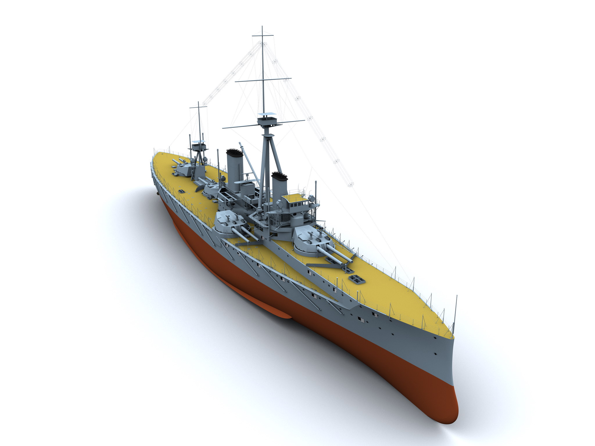
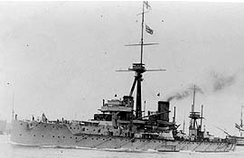
H.M.S. Dreadnought was a British battleship of the Royal Navy whose design had a revolutionary impact on not only her own navy, but of many others.
The only member of her class, she was the first all-big-gun battleship to be laid down, launched, and commissioned. Her design also featured the novel elements of turbine propulsion and rendered all other battleships building or in service obsolescent, thus lending her name to an entire generation of all-big-gun warships: all which came after her were branded "Dreadnoughts", and all those before as "Pre-Dreadnoughts."

H.M.S. Dreadnought (1906)
Pendant Number:00 (1914)
56 (Jan 1918)
73 (Apr 1918)[1]
Builder:Portsmouth Royal Dockyard[2]
Ordered:1905
Laid down:2 Oct, 1905[3]
Launched:10 Feb, 1906[4]
Commissioned:2 Dec, 1906
Sold:9 May, 1921[5]
Fate:Broken up
Construction
Extraordinary steps were taken to ensure a swift delivery time before construction even started. The hull had been designed to be as simple as possible while being able to withstand the shock of firing a broadside of eight guns. The variety of types of steel size was kept to a minimum and where possible the size of armour plating, in its various thicknesses, was standardised. As much materiel as possible was ordered in quantity and stockpiled in advance. By the time construction began, £12,217 had been spent on labour; £29,078 had been spent on materiel and 1,100 men had been engaged.[6]
She was the seventh ship to bear the name Dreadnought in the Royal Navy.
Captains
Dates of appointment given:
Bloomsbury Hoax
On 10 February, 1910 she attracted the attention of notorious hoaxer Horace de Vere Cole, who persuaded the Royal Navy to arrange for a party of Abyssinian royals to be given a tour of a ship atWeymouth. In reality, the "Abyssinian royals" were some of Cole's friends in blackface and disguise, including a young Virginia Woolf and her Bloomsbury Group friends; it became known as theDreadnought hoax. Cole had picked Dreadnought because she was at that time the most prominent and visible symbol of Britain's naval might.
Pre war
On 27 July, 1910, soon after ascending to the throne, HM King George V visited Dreadnought at Torbay. For two days Dreadnought, under the command of Captain Herbert Richmond in company with the Commander-in-Chief William May went to sea on exercises.
In mid-1913, she was serving as flagship of Fourth Battle Squadron.[18]
War Service
On 19 March 1915, Dreadnought was still serving as part of the Fourth Battle Squadron and under the command of Captain Alderson when she rammed and sank U 29, which had fired torpedoes at the ships as they steamed back to Cromarty.[19]
Post-War
Dreadnought reduced to C. & M. Party at Rosyth on 31 March, 1920.[20]
Boats
In July 1914, the ship was appropriated 42-foot motor launch No. 258, though the boat was not yet delivered from the contractor.[21]
Navigational Equipment
The ship was one of seven which tested Willis and Robinson Electric Revolution Telegraphs. Testing was completed in late 1913.[22]
Performance
The ship was applauded for being easy to handle, almost like a destroyer, her design permitting easy visibility from the bridge. In turning trials, six runs were tried. The interpretation of "Distance in turning" is not clear.[23]
RunSpeed
in knotsDistance
in turningTime to turn
4 pts
117.72359 yds36.0 secs
214.8268 yds25.0 secs
310.9156 yds27.5 secs
49.02165 yds32.7 secs
58.9175 yds34.8 secs
67.71169 yds39.0 secs
Habitability
Lieutenant Lionel Dawson later recalled that Dreadnought "was a very uncomfortable ship." And:
The mess-decks were small and cramped, and, being aft, most inconvenient for the internal economy of the ship.
She was the first battleship in which the greater part of the officers' quarters were forward. It was by no means an unqualified advantage. Cabins were small and distributed all over the ship, wherever room could be found for them. My first cabin was in one of the mess-decks aft, and a horrible place it was to live in. From it one had to walk half the length of the ship to the officers' bathroom. My second was forward, all mixed up with the chain cables and a Diesel engine that provided an auxiliary supply light for the fore part of the ship when necessary, and whose vibrations made life in its vicinity very uncomfortable when it was running. There was a good wardroom forward—very light and airy, and on the upper deck; the Admiral's quarters, on the deck below, were also good.[24]
In late 1913, a study aboard Dreadnought of excessively low humidity in winter attributable to heating prompted an Admiralty Order that mess decks be kept no warmer than 60 degrees Fahrenheit, rather than the previous standard of 70 degrees. It was noted that American experiments with humidifying equipment had proven problematic.[25]
Radio
In 1908, the ship was one of just nine equipped with the "C" Tune Gear, capable of transmitting (only?) on "S", "U" and "W" tunes. It was to receive a Service Mark II set in 1909.[26]
At the end of 1909, she was to receive one of eleven Short Distance Radio Sets, to be installed at her next refit behind armour near the fore bridge, intended to supplant flag signaling.{ARTS1909|Wireless Appendix, p. 25}} In mid-1913, this gear was redesignated as Type 3.[27]
Armament
In early 1913, new pattern G. 329 trainer's telescopes of 2.5 power and 20 degree field were issued to these and many other capital ships, to replace the 5/12, 5/15 and 5/21 variable power G.S. telescopes that had previously been in use.[28]
Main Battery
The five turrets were labelled "A", "X", and "Y" on the centre line and "P" to port and "Q" to starboard.[29]
This section is sourced in The Sight Manual, 1916 except as otherwise cited.[30]
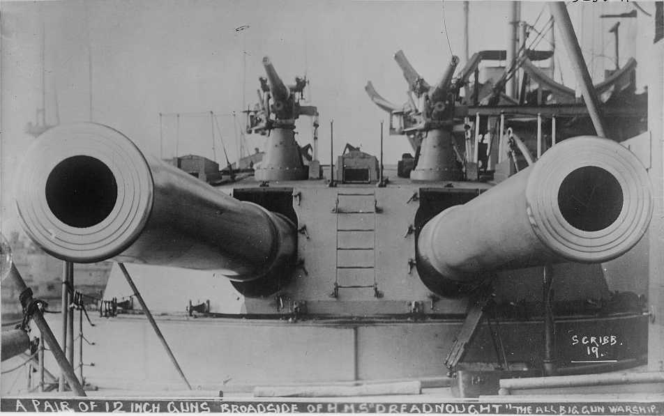
The ten 12-in guns were Mark X mounted in B VIII turrets designed by Vickers and tendered in July, 1905. "X" and "Y" mountings were built by Vickers at a cost of £69,860 per mounting. Armstrong constructed "A", "P" and "Q" mountings, at a tendered cost of £70,092.[31] The mountings could elevate between 13.5 degrees and 5 degrees depression.
The gun sights were gear-worked sights with telescopes (periscopes would not debut until St. Vincent) with a range gearing constant of 32 and limited to 15 degrees elevation, but 6 degree super-elevation prisms would have been provided by 1916.
The deflection gearing constant was 82.5 in the side positions and 82.66 in the centre, with 1 knot equalling 2.53 arc minutes, calculated as 2700 fps at 5000 yards. Range drums were provided for 2 CRH projectiles at full charge at 2650 fps, reduced charge at 2225 fps, as well as 12-pdr guns on the roof and 6-pdr sub-calibre guns and .303-in aiming rifles. By some time in 1916, dials and drums were on hand for 4 CRH heads.
Muzzle velocity was corrected by adjustable pointer between +/- 75 fps. The adjustable temperature scale plate could vary between 18 to 122 degrees Fahrenheit, and a "C" corrector could alter the ballistic coefficient between -10% and +15%.
Drift was corrected by inclining the sight bracket by 2 degrees and using 1 knot permanent left deflection when firing 4 CRH shells.
The side position sighting lines were 36 inches above and 41.35 inches abreast the bore, and the central scopes were 36.75 inches above and 42 inches abreast. The side sights had dials and were set from the side, and the central sights had drums and were set from the front. Oddly, the deflection dials were set without use of handwheels or gearing.
An arrow etched in her deflection dial at 1 knot right was inscribed, "Zero for sight testing."
The first shells provided were 2crh until 1915 or 1916 when 4crh shells were supplied. These later shells were more aerodynamically efficient and manufactured to tighter tolerances, yielding an increase in range from 16,450 to 18,850 yards and improving accuracy.[32]
The layout of guns offered an 8 gun broadside from 60 degrees before the beam to 50 degrees abaft, at which point it reduced to 6 guns aft and 4 guns forward.[33]
The hydraulic controls in training and elevation were no more agile than in preceding ships, and the inability to smoothly follow a point of aim obviated the goal of continuous aim for the fastest possible salvo firing. Dreadnought used two three-cylinder training engines controlled by a two-position lever for direction and a hand-wheel operated "creep valve" to control the speed of traversal. This clumsy control method was to be superseded by a hand wheel which controlled both functions. Dreadnought received this in a retrofit by November, 1909.[34]
Secondary Battery
The high velocity 12-pdr 18 cwt guns were mounted on P IV* mountings, similar to those in the Lord Nelson, King Edward VII and Minotaur classes.[35]
The mounting could elevate to 20 degrees and depress to 10 degrees, but though its sight could match the 20 degree elevation, the range dial was only graduated to 14.5 degrees (7,900 yards). This was fine, as there was limited fire control support provided for them and the weapons proved to have little effectiveness at the ranges where torpedo attack became deeply worrying.
The gear-worked sights were similar to the P IV type, but added a cross-connected trainer's sight. They had a range gearing contant of 54 and range dials for 2550 fps, 1962 fps, and 1-in and .303-in aiming rifles. The first series produced corrected for MV with detachable cams for 2600, 2575, 2550, 2525 and 2500 fps. The second series replaced these with an adjustable pointer for +/- 50 fps.
The deflection gearing constant was 63.38 with 1 knot equal to 2.96 arc minutes, corresponding to 2600 fps at 2000 yards. Drift was corrected by inclining the sight carrier arm 2 degrees.
The layer's and trainer's sight lines were 10 inches above the bore, and 10.25 inches abreast.
The sight lacked a "C" corrector. There do not seem to be temperature correctors or open sights.
The gun was worked by a crew of six and could fire about 20 rounds per minute.[36]
Torpedoes
Dreadnought carried five submerged 18-in tubes:[37]
In 1913, it was approved as part of a general reallocation of 18-in torpedoes, to replace the Mark VI** H. or 18-in Mark VI*** H. torpedoes on Neptune, St. Vincent, Bellerophon and Dreadnought classes with with Mark VII* or Mark VI**.[39] The Admiralty had simultaneously imposed a limit of gyro angle settings of 20 degrees in these same ships. This restriction was lifted just before the war.[40]
In 1916-1917, the stern tube was removed altogether.[41]
Fire Control
Rangefinders
Dreadnought was completed with two 9-foot rangefinders, and a variety of other 9-foot instruments were added over her service life.[42]
Rangefinders
Period9-foot Barr and Stroud R.F.s
1906-1912one F.Q. 2 on M.P. 2 mounting in fore top
one F.Q. 2 on M.P. 2 mounting on signal tower
1912-1915one F.Q. 2 on Argo Mounting in fore top
one F.Q. 2 on M.P. 2 mounting on signal tower
one F.T. 8 on M.G. 3 in "A" turret
one F.Q. 2 on M.N. 1 on compass platform
1915-1918one F.Q. 2 on Argo Mounting in fore top
five F.T. 8s on M.G. 3s in the turrets (fitted in 1915)
one F.Q. 2 on M.N. 1 on compass platform
1915-1918one F.Q. 2 on Argo Mounting in fore top
one F.T. 24 on M.G. 3 in "A" turret
four F.T. 8s on M.G. 3s in other turrets
one F.Q. 2 on M.N. 1 on compass platform
Evershed Bearing Indicators
Dreadnought was fitted with this equipment early in 1914.
Her transmitting positions were
In 1917, it was approve that all ships of Dreadnought class and later should have Evershed equipment added to their C.T., able to communicate with either the fore top or a controlling turret. If there were not enough room in the C.T., a bearing plate with open sights and 6-power binoculars would be added to the C.T.. At the same time, all directors were to be fitted with receivers and, "as far as possible", ships were to have fore top, G.C.T. and controlling turrets fitted to transmit as well as receive, though this was noted as being impossible in some earlier ships.[44]
Spotting
In late 1913, the ship landed a Pattern 740 Zeiss stereo spotting telescope Mark II at Portsmouth in order to take on a Ross Pattern 873 model for a three-month comparative evaluation.[45]
At some point, Dreadnought was equipped with a pair of Mechanical Aid-to-Spotter Mark Is, one on each side of the foretop, keyed off the Evershed rack on the director. As the need for such gear was apparently first identified in early 1916, it seems likely that these installations were effected well after Jutland.[46]
In 1917, it was decided that these should have mechanical links from the director and pointers indicating the aloft Evershed's bearing.[47]
Gunnery Control
Dreadnought's control arrangements were as follows.[48]
Control Positions
Control Groups
The five 12-in turrets were each a separate group with a local C.O.S.[Inference] so that it could be connected to
Main Battery
Dreadnought was completed without a director,[51] but between April and May 1916 was fitted with a geared tripod-type director in a light aloft tower over the foretop[52][53] along with a directing gun in "Y" turret.[54] The battery was not divisible into groups for split director firing.[55]
The main control positions were in the fore top and on a platform on the roof of the signal tower, each with a 9 foot FQ2 rangefinder. The aft control position was eventually done away with.[56]
The turret Elevation Receivers were pattern number H. 2, capable of matching the 13.5 degree elevation limit of the mountings. The Training Receivers were the single dial type, pattern number 7.[57]
Secondary Battery
The 12-pdrs never had directors installed.[58]
Torpedo Control
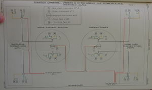

Torpedo Control Systems in Invincible class[59].
Dreadnought was similar, but lacked facilities in the conning tower.
Arrangements were generally similar to those in the Invincible class, which were documented in the Annual Report of the Torpedo School, 1913, except that she had no control position in the conning tower — all control was asserted from the torpedo control tower aft.[60]
By the end of 1917, common torpedo control additions to all capital ships were to be adopted where not already in place. Those for Dreadnoughtand later classes with 18-in tubes were to include:[61]
Like all large British ships of the era prior to King George V and Queen Mary,[62] Dreadnought had 2 T.S.es on her middle deck, the main one in the lower conning tower and one in the lower signal tower.[63]
The placement on the middle deck left the T.S.es above the armour deck, although they had some added splinter shielding and the main T.S. was somewhat covered by the "A" barbette and the secondary one by "P" and "Q" barbettes. However, this was recognized as a problem, and the main T.S. was moved to the lower deck in 1908-1909.[64]
The T.S.es had voicepipe connections to the control positions, possibly just the nearest one.[65]
Dreyer Table
Dreadnought was retro-fitted with a Mark I Dreyer Table sometime around 1913,[66][67] but was never given Dreyer Turret Control Tables[68]
Fire Control Instruments
By 1909, Dreadnought had Vickers, Son and Maxim instruments for range, orders and deflection, and Barr and Stroud instruments for rate.[69]
The equipment listed in the Handbook for Fire Control Instruments, 1909 is as follows (Vickers, unless otherwise noted):[70]
In 1908-9, Barr and Stroud rate instruments were added between T.S.es and control positions.[73]
In 1911, it was decided that the ship should be fitted with "range, buzzer and bearing instruments for communication between control positions, control turrets and transmitting and plotting stations." It was further detailed that she should have Siemens Pattern 120 turret fire gongs adapted so they could be rung mechanically.[74]
In 1912-1913, the turrets were given a means of local control, wherein range and deflection transmitters in the turrets could drive the receivers at the gunsights. Presumably, this also involved installation of a COS and involved a local firing push. At the same time, "A" and "Y" turrets were equipped to act as alternate control positions, being given additional instruments, navyphones and voicepipes to communicate with the TS, and probably requiring a fancier C.O.S. in each T.S..[75]
Alterations
John Roberts compiled a variety of important modifications to Dreadnought over her service life:[76]
Fire Control Systems
Directors
Main Battery
Dreadnought was completed without a director but by mid 1916 was fitted with a geared tripod-type director in a light aloft tower on the fore top along with a directing gun in "Y" turret.[83][84] The battery was not divisible into groups for split director firing.[85] The main director was fitted with Henderson Firing Gear in 1917-1918.[86]
Secondary Battery
The 12-pdrs never had directors installed.[87]
Control was exercised from either the spotting or main top, with the control officer in the top communicating via navyphone to the sightsetters of his assigned groups of 12-pdrs who wore telaupads.[88]
Torpedo Control
Transmitting Stations
Dreyer Table
Dreadnought was retro-fitted around mid 1916[89] with a Mark I Dreyer Table, but was never given Dreyer Turret Control Tables.[90]
Miscellaneous
Dreadnought was fitted with Evershed Bearing Indicators in fore top between in extended work between a stop in Portsmouth 9 August, 1913 and one in Gibraltar, 2 April, 1914.
Footnotes
Bibliography
::::::::::::::::::::::::::::::::::::::::::::::::::::::::::::::::::::::::::::::::::::::::::::::::::::::::::::::::::::::::::::::::::::::::::::::::::::::::::::
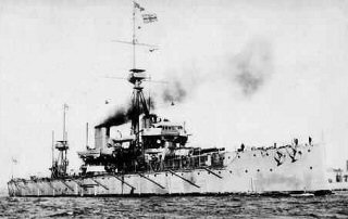
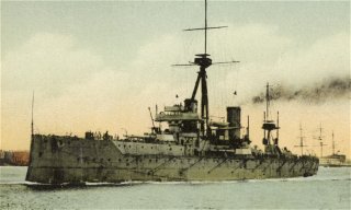
HMS Dreadnaught shown left flying an Admiral's flag
In 1905 the British Admiralty approved plans for the worlds first dreadnaught. The first battleship to be powered by Turbine propulsion system, which gave her a speed of 21.5 knots during her trials, which compared to the earlier battleship speeds of 17 to 18 knots. It took just one year to complete the construction of HMS Dreadnaught, from the beginning of laying her keel to the ship being completed and only six months later she entered service. HMS Dreadnaught was the flagship of the the 4th battle squadron at the outbreak of world war One and on the 18th March 1915 she rammed and sunk the German U-Boat U29in the North Sea. HMS Dreadnaught missed the Battle of Jutland as she was in refit due to her poor condition and in August 1917 she was transferred to the Navy Reserve. Finally sold for breaking up in May 1921. and finally scrapped in 1923.
The ninth “DREADNOUGHT” is a 10-gun turbine battleship launched at Portsmouth in 1906. She is of 17,900 tons, 27,500 horse-power, and 22 knots speed. Her length, beam, and draught were 490ft., 82ft., and 26ft. This vessel represented an important departure from the comtemporary battleship design, and as she was the first vessel of the twentieth century to embody the all-big-gun principle, as well as to be fitted with turbine machinery, much attention was concentrated upon her trials and subsequent behaviour. On August 5th, 1907, His Majesty, the late king Edward the Seventh, accompanied by Her Majesty Queen Alexandra, Their Royal Highnesses the Prince of Wales, Princess Victoria, Prince Edward of Wales and H. R. H. the Duke of Connaught visited H.M.S. “Dreadnought” at Spithead. Their Majesties were received by the Board of Admiralty, Vice-Admiral Sir Francis Bridgeman, commanding the home fleet, and Captain R. H. Bacon, who commanded the ship. The Standard having being broken, Their Majesties inspected the battleship, and proceeding for a short cruise, witnessed some firing by the 12-in. guns, and also a series of exercises performed by the Submarine Flotilla. Soon after his accession to the Throne, His Majesty King George the fifth honoured the Home Fleet with a visit at Torbay. On July 27th and 28th, 1910, the “Dreadnought,” commanded by Captain H. W. Richmond, flying the flag of Admiral Sir William H. May, the Commander-in-Chief, proceeded to sea for various exercises with the fleet, and His Majesty the King was graciously pleased to go to sea and fly his Royal Standard in the “Dreadnought” on both these occasions.
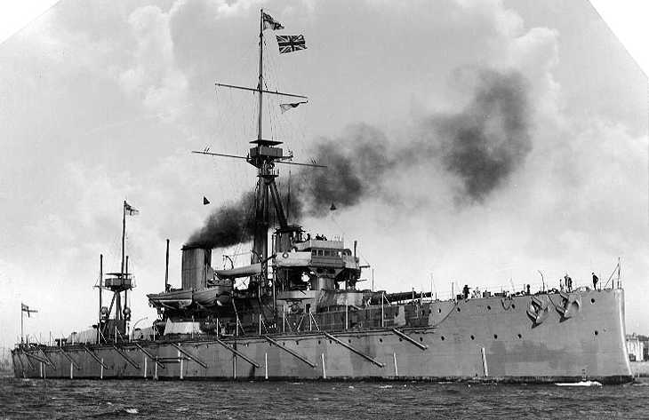
HMS Dreadnought
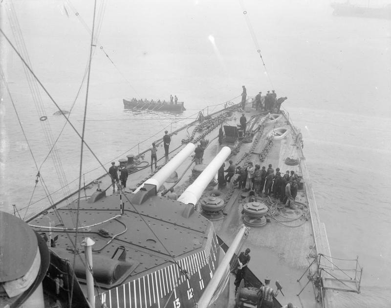
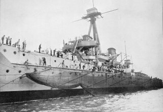 HMS Dreadnought with Torpedo Nets Out.
 HMS Dreadnought
@scorpionx @Jessica_L @AUSTERLITZ @Slav Defence @jaibi @Secur @RAMPAGE @Parul @Chak Bamu @chak de INDIA
The only member of her class, she was the first all-big-gun battleship to be laid down, launched, and commissioned. Her design also featured the novel elements of turbine propulsion and rendered all other battleships building or in service obsolescent, thus lending her name to an entire generation of all-big-gun warships: all which came after her were branded "Dreadnoughts", and all those before as "Pre-Dreadnoughts."
H.M.S. Dreadnought (1906)
Pendant Number:00 (1914)
56 (Jan 1918)
73 (Apr 1918)[1]
Builder:Portsmouth Royal Dockyard[2]
Ordered:1905
Laid down:2 Oct, 1905[3]
Launched:10 Feb, 1906[4]
Commissioned:2 Dec, 1906
Sold:9 May, 1921[5]
Fate:Broken up
Construction
Extraordinary steps were taken to ensure a swift delivery time before construction even started. The hull had been designed to be as simple as possible while being able to withstand the shock of firing a broadside of eight guns. The variety of types of steel size was kept to a minimum and where possible the size of armour plating, in its various thicknesses, was standardised. As much materiel as possible was ordered in quantity and stockpiled in advance. By the time construction began, £12,217 had been spent on labour; £29,078 had been spent on materiel and 1,100 men had been engaged.[6]
She was the seventh ship to bear the name Dreadnought in the Royal Navy.
Captains
Dates of appointment given:
- Captain Reginald H. S. Bacon, 2 July, 1906.[7]
- Captain Charles E. Madden, 12 August, 1907.[8]
- Captain A. Gordon H. W. Moore, 1 December, 1908.[9]
- Captain Herbert W. Richmond, 30 July, 1909.[10]
- Captain Sydney R. Fremantle, 28 March, 1911.[11]
- Captain Wilmot S. Nicholson, 17 December, 1912.[12]
- Captain William J. S. Alderson, 1 July, 1914.[13]
- Captain John W. L. McClintock, 19 July, 1916.[14]
- Captain Arthur C. S. H. D'Aeth, 1 December, 1916.[15]
- Captain Thomas E. Wardle, January, 1918.[16]
- Captain Maurice S. FitzMaurice, April, 1918.[17]
- Captain Robert H. Coppinger, February, 1919.[17]
Bloomsbury Hoax
On 10 February, 1910 she attracted the attention of notorious hoaxer Horace de Vere Cole, who persuaded the Royal Navy to arrange for a party of Abyssinian royals to be given a tour of a ship atWeymouth. In reality, the "Abyssinian royals" were some of Cole's friends in blackface and disguise, including a young Virginia Woolf and her Bloomsbury Group friends; it became known as theDreadnought hoax. Cole had picked Dreadnought because she was at that time the most prominent and visible symbol of Britain's naval might.
Pre war
On 27 July, 1910, soon after ascending to the throne, HM King George V visited Dreadnought at Torbay. For two days Dreadnought, under the command of Captain Herbert Richmond in company with the Commander-in-Chief William May went to sea on exercises.
In mid-1913, she was serving as flagship of Fourth Battle Squadron.[18]
War Service
On 19 March 1915, Dreadnought was still serving as part of the Fourth Battle Squadron and under the command of Captain Alderson when she rammed and sank U 29, which had fired torpedoes at the ships as they steamed back to Cromarty.[19]
Post-War
Dreadnought reduced to C. & M. Party at Rosyth on 31 March, 1920.[20]
Boats
In July 1914, the ship was appropriated 42-foot motor launch No. 258, though the boat was not yet delivered from the contractor.[21]
Navigational Equipment
The ship was one of seven which tested Willis and Robinson Electric Revolution Telegraphs. Testing was completed in late 1913.[22]
Performance
The ship was applauded for being easy to handle, almost like a destroyer, her design permitting easy visibility from the bridge. In turning trials, six runs were tried. The interpretation of "Distance in turning" is not clear.[23]
RunSpeed
in knotsDistance
in turningTime to turn
4 pts
117.72359 yds36.0 secs
214.8268 yds25.0 secs
310.9156 yds27.5 secs
49.02165 yds32.7 secs
58.9175 yds34.8 secs
67.71169 yds39.0 secs
Habitability
Lieutenant Lionel Dawson later recalled that Dreadnought "was a very uncomfortable ship." And:
The mess-decks were small and cramped, and, being aft, most inconvenient for the internal economy of the ship.
She was the first battleship in which the greater part of the officers' quarters were forward. It was by no means an unqualified advantage. Cabins were small and distributed all over the ship, wherever room could be found for them. My first cabin was in one of the mess-decks aft, and a horrible place it was to live in. From it one had to walk half the length of the ship to the officers' bathroom. My second was forward, all mixed up with the chain cables and a Diesel engine that provided an auxiliary supply light for the fore part of the ship when necessary, and whose vibrations made life in its vicinity very uncomfortable when it was running. There was a good wardroom forward—very light and airy, and on the upper deck; the Admiral's quarters, on the deck below, were also good.[24]
In late 1913, a study aboard Dreadnought of excessively low humidity in winter attributable to heating prompted an Admiralty Order that mess decks be kept no warmer than 60 degrees Fahrenheit, rather than the previous standard of 70 degrees. It was noted that American experiments with humidifying equipment had proven problematic.[25]
Radio
In 1908, the ship was one of just nine equipped with the "C" Tune Gear, capable of transmitting (only?) on "S", "U" and "W" tunes. It was to receive a Service Mark II set in 1909.[26]
At the end of 1909, she was to receive one of eleven Short Distance Radio Sets, to be installed at her next refit behind armour near the fore bridge, intended to supplant flag signaling.{ARTS1909|Wireless Appendix, p. 25}} In mid-1913, this gear was redesignated as Type 3.[27]
Armament
In early 1913, new pattern G. 329 trainer's telescopes of 2.5 power and 20 degree field were issued to these and many other capital ships, to replace the 5/12, 5/15 and 5/21 variable power G.S. telescopes that had previously been in use.[28]
Main Battery
The five turrets were labelled "A", "X", and "Y" on the centre line and "P" to port and "Q" to starboard.[29]
This section is sourced in The Sight Manual, 1916 except as otherwise cited.[30]
The ten 12-in guns were Mark X mounted in B VIII turrets designed by Vickers and tendered in July, 1905. "X" and "Y" mountings were built by Vickers at a cost of £69,860 per mounting. Armstrong constructed "A", "P" and "Q" mountings, at a tendered cost of £70,092.[31] The mountings could elevate between 13.5 degrees and 5 degrees depression.
The gun sights were gear-worked sights with telescopes (periscopes would not debut until St. Vincent) with a range gearing constant of 32 and limited to 15 degrees elevation, but 6 degree super-elevation prisms would have been provided by 1916.
The deflection gearing constant was 82.5 in the side positions and 82.66 in the centre, with 1 knot equalling 2.53 arc minutes, calculated as 2700 fps at 5000 yards. Range drums were provided for 2 CRH projectiles at full charge at 2650 fps, reduced charge at 2225 fps, as well as 12-pdr guns on the roof and 6-pdr sub-calibre guns and .303-in aiming rifles. By some time in 1916, dials and drums were on hand for 4 CRH heads.
Muzzle velocity was corrected by adjustable pointer between +/- 75 fps. The adjustable temperature scale plate could vary between 18 to 122 degrees Fahrenheit, and a "C" corrector could alter the ballistic coefficient between -10% and +15%.
Drift was corrected by inclining the sight bracket by 2 degrees and using 1 knot permanent left deflection when firing 4 CRH shells.
The side position sighting lines were 36 inches above and 41.35 inches abreast the bore, and the central scopes were 36.75 inches above and 42 inches abreast. The side sights had dials and were set from the side, and the central sights had drums and were set from the front. Oddly, the deflection dials were set without use of handwheels or gearing.
An arrow etched in her deflection dial at 1 knot right was inscribed, "Zero for sight testing."
The first shells provided were 2crh until 1915 or 1916 when 4crh shells were supplied. These later shells were more aerodynamically efficient and manufactured to tighter tolerances, yielding an increase in range from 16,450 to 18,850 yards and improving accuracy.[32]
The layout of guns offered an 8 gun broadside from 60 degrees before the beam to 50 degrees abaft, at which point it reduced to 6 guns aft and 4 guns forward.[33]
The hydraulic controls in training and elevation were no more agile than in preceding ships, and the inability to smoothly follow a point of aim obviated the goal of continuous aim for the fastest possible salvo firing. Dreadnought used two three-cylinder training engines controlled by a two-position lever for direction and a hand-wheel operated "creep valve" to control the speed of traversal. This clumsy control method was to be superseded by a hand wheel which controlled both functions. Dreadnought received this in a retrofit by November, 1909.[34]
Secondary Battery
The high velocity 12-pdr 18 cwt guns were mounted on P IV* mountings, similar to those in the Lord Nelson, King Edward VII and Minotaur classes.[35]
The mounting could elevate to 20 degrees and depress to 10 degrees, but though its sight could match the 20 degree elevation, the range dial was only graduated to 14.5 degrees (7,900 yards). This was fine, as there was limited fire control support provided for them and the weapons proved to have little effectiveness at the ranges where torpedo attack became deeply worrying.
The gear-worked sights were similar to the P IV type, but added a cross-connected trainer's sight. They had a range gearing contant of 54 and range dials for 2550 fps, 1962 fps, and 1-in and .303-in aiming rifles. The first series produced corrected for MV with detachable cams for 2600, 2575, 2550, 2525 and 2500 fps. The second series replaced these with an adjustable pointer for +/- 50 fps.
The deflection gearing constant was 63.38 with 1 knot equal to 2.96 arc minutes, corresponding to 2600 fps at 2000 yards. Drift was corrected by inclining the sight carrier arm 2 degrees.
The layer's and trainer's sight lines were 10 inches above the bore, and 10.25 inches abreast.
The sight lacked a "C" corrector. There do not seem to be temperature correctors or open sights.
The gun was worked by a crew of six and could fire about 20 rounds per minute.[36]
Torpedoes
Dreadnought carried five submerged 18-in tubes:[37]
- two forward, depressed 1 degree and angled 15 degrees before the beam, axis of tube 11 foot 2 inches below load water line and 2 foot 5 inches above the deck.
- two aft, depressed 1 degree and angled at 15 degrees abaft the beam; axis of tube 9 feet 9 inches below load water line and 2 foot 5 inches above the deck.
- one in the stern, depressed 1 degree; axis of tube 8 feet 6 inches below load water line and 1 foot 9 inches above the deck.
In 1913, it was approved as part of a general reallocation of 18-in torpedoes, to replace the Mark VI** H. or 18-in Mark VI*** H. torpedoes on Neptune, St. Vincent, Bellerophon and Dreadnought classes with with Mark VII* or Mark VI**.[39] The Admiralty had simultaneously imposed a limit of gyro angle settings of 20 degrees in these same ships. This restriction was lifted just before the war.[40]
In 1916-1917, the stern tube was removed altogether.[41]
Fire Control
Rangefinders
Dreadnought was completed with two 9-foot rangefinders, and a variety of other 9-foot instruments were added over her service life.[42]
Rangefinders
Period9-foot Barr and Stroud R.F.s
1906-1912one F.Q. 2 on M.P. 2 mounting in fore top
one F.Q. 2 on M.P. 2 mounting on signal tower
1912-1915one F.Q. 2 on Argo Mounting in fore top
one F.Q. 2 on M.P. 2 mounting on signal tower
one F.T. 8 on M.G. 3 in "A" turret
one F.Q. 2 on M.N. 1 on compass platform
1915-1918one F.Q. 2 on Argo Mounting in fore top
five F.T. 8s on M.G. 3s in the turrets (fitted in 1915)
one F.Q. 2 on M.N. 1 on compass platform
1915-1918one F.Q. 2 on Argo Mounting in fore top
one F.T. 24 on M.G. 3 in "A" turret
four F.T. 8s on M.G. 3s in other turrets
one F.Q. 2 on M.N. 1 on compass platform
Evershed Bearing Indicators
Dreadnought was fitted with this equipment early in 1914.
Her transmitting positions were
- Fore control platform (transmitters to port and starboard with a local switch to select the one to use)
- "A" turret
- "X" turret
- "Y" turret
- Upper aft conning tower
In 1917, it was approve that all ships of Dreadnought class and later should have Evershed equipment added to their C.T., able to communicate with either the fore top or a controlling turret. If there were not enough room in the C.T., a bearing plate with open sights and 6-power binoculars would be added to the C.T.. At the same time, all directors were to be fitted with receivers and, "as far as possible", ships were to have fore top, G.C.T. and controlling turrets fitted to transmit as well as receive, though this was noted as being impossible in some earlier ships.[44]
Spotting
In late 1913, the ship landed a Pattern 740 Zeiss stereo spotting telescope Mark II at Portsmouth in order to take on a Ross Pattern 873 model for a three-month comparative evaluation.[45]
At some point, Dreadnought was equipped with a pair of Mechanical Aid-to-Spotter Mark Is, one on each side of the foretop, keyed off the Evershed rack on the director. As the need for such gear was apparently first identified in early 1916, it seems likely that these installations were effected well after Jutland.[46]
In 1917, it was decided that these should have mechanical links from the director and pointers indicating the aloft Evershed's bearing.[47]
Gunnery Control
Dreadnought's control arrangements were as follows.[48]
Control Positions
- Fore top
- Main top
- "A" turret (after 1912-13)
- "Y" turret (ditto)[49]
Control Groups
The five 12-in turrets were each a separate group with a local C.O.S.[Inference] so that it could be connected to
- Forward T.S.
- After T.S.
- Local control from officer's position within turret
Main Battery
Dreadnought was completed without a director,[51] but between April and May 1916 was fitted with a geared tripod-type director in a light aloft tower over the foretop[52][53] along with a directing gun in "Y" turret.[54] The battery was not divisible into groups for split director firing.[55]
The main control positions were in the fore top and on a platform on the roof of the signal tower, each with a 9 foot FQ2 rangefinder. The aft control position was eventually done away with.[56]
The turret Elevation Receivers were pattern number H. 2, capable of matching the 13.5 degree elevation limit of the mountings. The Training Receivers were the single dial type, pattern number 7.[57]
Secondary Battery
The 12-pdrs never had directors installed.[58]
Torpedo Control

Torpedo Control Systems in Invincible class[59].
Dreadnought was similar, but lacked facilities in the conning tower.
Arrangements were generally similar to those in the Invincible class, which were documented in the Annual Report of the Torpedo School, 1913, except that she had no control position in the conning tower — all control was asserted from the torpedo control tower aft.[60]
By the end of 1917, common torpedo control additions to all capital ships were to be adopted where not already in place. Those for Dreadnoughtand later classes with 18-in tubes were to include:[61]
- duplication of firing circuits and order and gyro angle instruments to allow all tubes to be directed from either C.T. or T.C.T.
- navyphones from both control positions to all tube positions
- bearing instruments between "control position, and R.F., and course and speed of enemy instruments where applicable, between the transmitting stations and the control positions."
- range circuits between R.F.s and control positions
Like all large British ships of the era prior to King George V and Queen Mary,[62] Dreadnought had 2 T.S.es on her middle deck, the main one in the lower conning tower and one in the lower signal tower.[63]
The placement on the middle deck left the T.S.es above the armour deck, although they had some added splinter shielding and the main T.S. was somewhat covered by the "A" barbette and the secondary one by "P" and "Q" barbettes. However, this was recognized as a problem, and the main T.S. was moved to the lower deck in 1908-1909.[64]
The T.S.es had voicepipe connections to the control positions, possibly just the nearest one.[65]
Dreyer Table
Dreadnought was retro-fitted with a Mark I Dreyer Table sometime around 1913,[66][67] but was never given Dreyer Turret Control Tables[68]
Fire Control Instruments
By 1909, Dreadnought had Vickers, Son and Maxim instruments for range, orders and deflection, and Barr and Stroud instruments for rate.[69]
The equipment listed in the Handbook for Fire Control Instruments, 1909 is as follows (Vickers, unless otherwise noted):[70]
- Range transmitters: 10
- Deflection transmitters: 10
- Combined Range and Deflection receivers: 31
- C.O.S.: 8
- Check fire switches: 9
- Rate: 3 transmitters, 6 receivers (Barr and Stroud)
- Turret fire gongs: 15 with 5 keys (Siemens, plus 10 Vickers gongs fitted "as relays")
- Captain's Cease Fire Bells: 10 with 1 key (supplier not stated)
In 1908-9, Barr and Stroud rate instruments were added between T.S.es and control positions.[73]
In 1911, it was decided that the ship should be fitted with "range, buzzer and bearing instruments for communication between control positions, control turrets and transmitting and plotting stations." It was further detailed that she should have Siemens Pattern 120 turret fire gongs adapted so they could be rung mechanically.[74]
In 1912-1913, the turrets were given a means of local control, wherein range and deflection transmitters in the turrets could drive the receivers at the gunsights. Presumably, this also involved installation of a COS and involved a local firing push. At the same time, "A" and "Y" turrets were equipped to act as alternate control positions, being given additional instruments, navyphones and voicepipes to communicate with the TS, and probably requiring a fancier C.O.S. in each T.S..[75]
Alterations
John Roberts compiled a variety of important modifications to Dreadnought over her service life:[76]
- 1908-1909
- 1912-1913
- 30 April 1913
- 2 April 1914
- Evershed Bearing Indicators added to fore top
- 7 June 1915
- Fore top rebuilt to receive director tower
- 36-in searchlight platforms added to foremast struts
- 9-foot F.T. 8 R.F.s added to "P", "Q", "X", and "Y" turrets
- bridge wings removed
- searchlight control gear installation begins
- open sights added to all turrets
- 12-pdr guns removed from "A" turret and placed on quarterdeck
- two 6-pdr H.A. guns added to quarterdeck
- aft control position atop signal tower removed.[80]
- by mid 1916, perhaps ending on May 25th
- torpedo nets removed
- director for her main battery added to roof of fore top
- given a Dreyer Table Mark I in main T.S.[81]
- late 1916
- 6-pdr H.A. guns replaced by two 3-in H.A. guns
- 27 Jan 1917
- extra 0.75 to 1-in armor added to middle deck over magazines
- 19 August 1917
- anti-flash scuttles added to magazine doors
- Type 16 W/T installed in former Lamp Room
- Four 36-in searchlights replace main top with control position underneath
- stern torpedo tube removed
- upper 12-pdr magazine converted into T.S.
- Two 12-pdrs on quarterdeck converted to H.A. mountings
- pedestals for Evershed equipment added in fore bridge
- bearing indicators added to 3-in and 12-pdr H.A. guns
- Henderson gear being added to director
- adding a Sperry gyrocompass
- 1917
- deflection scales painted on "A" and "Y"
- 1917-1918
- semaphore machine on bridge removed
- 1 June 1918
- converted upper 12-pdr magazine to Type 31 W/T room
- 31 December 1918
- wind screen added to director tower
- turrets get open director sights
- open trainer's sight added to director canopy
- "A" turret's F.T. 8 R.F. replaced by 9-foot F.T. 24
- Henderson gear and Sperry gyro completely installed
- Argo R.F. moved to aft end of fore top, able to train all around
- aircraft flying platforms added to "A" and "Y"
- new 36-in searchlights installed
Fire Control Systems
Directors
Main Battery
Dreadnought was completed without a director but by mid 1916 was fitted with a geared tripod-type director in a light aloft tower on the fore top along with a directing gun in "Y" turret.[83][84] The battery was not divisible into groups for split director firing.[85] The main director was fitted with Henderson Firing Gear in 1917-1918.[86]
Secondary Battery
The 12-pdrs never had directors installed.[87]
Control was exercised from either the spotting or main top, with the control officer in the top communicating via navyphone to the sightsetters of his assigned groups of 12-pdrs who wore telaupads.[88]
Torpedo Control
Transmitting Stations
Dreyer Table
Dreadnought was retro-fitted around mid 1916[89] with a Mark I Dreyer Table, but was never given Dreyer Turret Control Tables.[90]
Miscellaneous
Dreadnought was fitted with Evershed Bearing Indicators in fore top between in extended work between a stop in Portsmouth 9 August, 1913 and one in Gibraltar, 2 April, 1914.
Footnotes
- ↑ Dittmar; Colledge. British Warships 1914–1919. p. 32.
- ↑ Conway's All the World's Fighting Ships 1906–1921. p. 21.
- ↑ Conway's All the World's Fighting Ships 1906–1921. p. 21.
- ↑ Dittmar; Colledge. British Warships 1914–1919. p. 32.
- ↑ Dittmar; Colledge. British Warships 1914–1919. p. 32.
- ↑ D. K. Brown. "DREADNOUGHT". p. 52.
- ↑ Bacon Service Record. The National Archives. ADM 196/42. f. 262.
- ↑ Madden Service Record. The National Archives. ADM 196/42. f. 83.
- ↑ Moore Service Record. The National Archives. ADM 196/42. f. 64.
- ↑ Richmond Service Record. The National Archives. ADM 196/43. f. 205.
- ↑ Fremantle Service Record. The National Archives. ADM 196/42. f. 473.
- ↑ Nicholson Service Record. The National Archives. ADM 196/43. f. 239.
- ↑ Alderson Service Record. The National Archives. ADM 196/42. f. 455.
- ↑ McClintock Service Record. The National Archives. ADM 196/43. f. 459.
- ↑ D'Aeth Service Record. The National Archives. ADM 196/44. f. 50.
- ↑ Wardle Service Record. The National Archives. ADM 196/44. f. 245.
- ↑ Mackie, Colin. ROYAL NAVY WARSHIPS.
- ↑ The Navy List (July, 1913). p. 303.
- ↑ Dreyer. The Sea Heritage. p. 94.
- ↑ The Navy List. (January, 1921). p. 762.
- ↑ Admiralty Weekly Order No. 122 of 10 July, 1914.
- ↑ Admiralty Weekly Order No. 607 of 24 Oct, 1913.
- ↑ Burt. British Battleships of World War One. p. 32.
- ↑ Dawson. p. 125.
- ↑ Admiralty Weekly Order No. 664 of 21 Nov, 1913.
- ↑ ARTS 1908 Wireless Appendix, p. 13.
- ↑ Admiralty Weekly Order No. 306 of 20 June, 1913.
- ↑ Admiralty Weekly Orders. 28 Feb, 1913. The National Archives. ADM 182/4.
- ↑ Manual of Gunnery in H.M. Fleet (Volume I), 1907, p. 1.
- ↑ The Sight Manual, 1916. pp. 4, 37-8, 105, 108-109.
- ↑ Anatomy of the Ship: The Battleship Dreadnought. p. 28.
- ↑ Anatomy of the Ship: The Battleship Dreadnought. pp. 28-9.
- ↑ Anatomy of the Ship: The Battleship Dreadnought. p. 28.
- ↑ Brooks. Dreadnought Gunnery and the Battle of Jutland, p. 46.
- ↑ The Sight Manual, 1916. p. 94, 108, Plate 47.
- ↑ Anatomy of the Ship: The Battleship Dreadnought. p. 29.
- ↑ Torpedo Manual, Vol. III, 1909. p. 265.
- ↑ Annual Report of the Torpedo School, 1909. pp. 13-4.
- ↑ Annual Report of the Torpedo School, 1913. p. 8.
- ↑ Admiralty Weekly Order No. 207 of 31 July 1914.
- ↑ Burt. British Battleships of World War One. p. 35.
- ↑ Anatomy of the Ship: The Battleship Dreadnought. pp. 28, 31.
- ↑ Handbook for Fire Control Instruments, 1914. pp. 33-4.
- ↑ Annual Report of the Torpedo School, 1917. p. 230.
- ↑ Admiralty Weekly Order No. 662 of 21 Nov, 1913.
- ↑ The Technical History and Index, Vol. 3, Part 23. pp. 25-6.
- ↑ Annual Report of the Torpedo School, 1917. p. 230.
- ↑ Handbook for Fire Control Instruments, 1914. p. 7.
- ↑ Anatomy of the Ship: The Battleship Dreadnought. p. 31.
- ↑ Handbook for Fire Control Instruments, 1914. p. 7.
- ↑ Anatomy of the Ship: The Battleship Dreadnought. p. ?.
- ↑ Burt. British Battleships of World War One. p. 29.
- ↑ Anatomy of the Ship: The Battleship Dreadnought. p. 31.
- ↑ The Director Firing Handbook. pp. 88, 142.
- ↑ The Director Firing Handbook. p. 88.
- ↑ Anatomy of the Ship: The Battleship Dreadnought. p. 30.
- ↑ The Director Firing Handbook. pp. 144, 146.
- ↑ The Director Firing Handbook. pp. 143.
- ↑ Annual Report of the Torpedo School, 1913. Plate 53.
- ↑ Annual Report of the Torpedo School, 1913. p. 102.
- ↑ Annual Report of the Torpedo School, 1917. p. 209. (C.I.O. 4212/17.).
- ↑ Handbook for Fire Control Instruments, 1914. pp. 6-7.
- ↑ Anatomy of the Ship: The Battleship Dreadnought. pp. 30, 74-6, 82-3.
- ↑ Anatomy of the Ship: The Battleship Dreadnought. p. 30.
- ↑ Anatomy of the Ship: The Battleship Dreadnought. p. 30.
- ↑ Handbook of Captain F. C. Dreyer's Fire Control Tables, 1918. p. 3.
- ↑ Anatomy of the Ship: The Battleship Dreadnought. p. 28.
- ↑ Handbook of Captain F. C. Dreyer's Fire Control Tables, 1918. p. 3.
- ↑ Handbook for Fire Control Instruments, 1909. p. 56.
- ↑ Handbook for Fire Control Instruments, 1909. p. 60.
- ↑ Handbook for Fire Control Instruments, 1909. p. 59.
- ↑ Handbook for Fire Control Instruments, 1914. p. 11.
- ↑ Anatomy of the Ship: The Battleship Dreadnought. p. 31.
- ↑ Annual Report of the Torpedo School, 1911. p. 95.
- ↑ Anatomy of the Ship: The Battleship Dreadnought. p. 31.
- ↑ Anatomy of the Ship: The Battleship Dreadnought. pp. 33-5.
- ↑ Anatomy of the Ship: The Battleship Dreadnought. p. 30.
- ↑ Anatomy of the Ship: The Battleship Dreadnought. p. 31.
- ↑ Anatomy of the Ship: The Battleship Dreadnought. p. 31.
- ↑ Anatomy of the Ship: The Battleship Dreadnought. p. 31.
- ↑ Anatomy of the Ship: The Battleship Dreadnought. p. 31.
- ↑ Admiralty Weekly Order No. 408 of 25 Sep, 1914.
- ↑ The Director Firing Handbook. pp. 88, 142.
- ↑ Anatomy of the Ship: The Battleship Dreadnought. p. 31.
- ↑ The Director Firing Handbook. p. 88.
- ↑ Anatomy of the Ship: The Battleship Dreadnought. p. 31.
- ↑ The Director Firing Handbook. p. 143.
- ↑ Anatomy of the Ship: The Battleship Dreadnought. p. 31.
- ↑ Anatomy of the Ship: The Battleship Dreadnought. p. 35.
- ↑ Handbook of Captain F. C. Dreyer's Fire Control Tables, 1918. p. 3.
Bibliography
- Dreyer, Admiral Sir Frederic C. (1955). The Sea Heritage: A Study of Maritime Warfare. London: Museum Press Limited.
- Admiralty, Gunnery Branch (1910). Handbook for Fire Control Instruments, 1909. Copy No. 173 is Ja 345a at Admiralty Library, Portsmouth, United Kingdom.
- Admiralty, Gunnery Branch (1914). Handbook for Fire Control Instruments, 1914. G. 01627/14. C.B. 1030. Copy 1235 at The National Archives. ADM 186/191.
- Admiralty, Gunnery Branch (1917). The Director Firing Handbook. O.U. 6125 (late C.B. 1259). Copy No. 322 at The National Archives. ADM 186/227.
- Admiralty, Gunnery Branch (1918). Handbook of Captain F. C. Dreyer's Fire Control Tables, 1918. C.B. 1456. Copy No. 10 at Admiralty Library, Portsmouth, United Kingdom.
- Admiralty, Technical History Section (1919). The Technical History and Index: Fire Control in H.M. Ships. Vol. 3, Part 23. C.B. 1515 (23) now O.U. 6171/14. At The National Archives. ADM 275/19.
- Brown, D K (January 1980). "The Design and Construction of the Battleship DREADNOUGHT". Warship IV (13): pp. 39–52.
- H.M.S. Vernon. Annual Report of the Torpedo School, 1906, with Appendix (Wireless Telegraphy). Copy 46 at The National Archives. ADM 189/26.
- H.M.S. Vernon. Annual Report of the Torpedo School, 1911, with Appendix (Wireless Telegraphy). Copy 15 at The National Archives. ADM 189/31.
- H.M.S. Vernon. (Feb 1914) Annual Report of the Torpedo School, 1913, with Appendix (Wireless Telegraphy). Copy 42 at The National Archives. ADM 189/33.
- Roberts, John A. (1992). Anatomy of the Ship: The Battleship Dreadnought. London: Conway Maritime Press. ISBN 085177895X. (on Amazon.com and Amazon.co.uk).
::::::::::::::::::::::::::::::::::::::::::::::::::::::::::::::::::::::::::::::::::::::::::::::::::::::::::::::::::::::::::::::::::::::::::::::::::::::::::::
HMS Dreadnaught shown left flying an Admiral's flag
In 1905 the British Admiralty approved plans for the worlds first dreadnaught. The first battleship to be powered by Turbine propulsion system, which gave her a speed of 21.5 knots during her trials, which compared to the earlier battleship speeds of 17 to 18 knots. It took just one year to complete the construction of HMS Dreadnaught, from the beginning of laying her keel to the ship being completed and only six months later she entered service. HMS Dreadnaught was the flagship of the the 4th battle squadron at the outbreak of world war One and on the 18th March 1915 she rammed and sunk the German U-Boat U29in the North Sea. HMS Dreadnaught missed the Battle of Jutland as she was in refit due to her poor condition and in August 1917 she was transferred to the Navy Reserve. Finally sold for breaking up in May 1921. and finally scrapped in 1923.
The ninth “DREADNOUGHT” is a 10-gun turbine battleship launched at Portsmouth in 1906. She is of 17,900 tons, 27,500 horse-power, and 22 knots speed. Her length, beam, and draught were 490ft., 82ft., and 26ft. This vessel represented an important departure from the comtemporary battleship design, and as she was the first vessel of the twentieth century to embody the all-big-gun principle, as well as to be fitted with turbine machinery, much attention was concentrated upon her trials and subsequent behaviour. On August 5th, 1907, His Majesty, the late king Edward the Seventh, accompanied by Her Majesty Queen Alexandra, Their Royal Highnesses the Prince of Wales, Princess Victoria, Prince Edward of Wales and H. R. H. the Duke of Connaught visited H.M.S. “Dreadnought” at Spithead. Their Majesties were received by the Board of Admiralty, Vice-Admiral Sir Francis Bridgeman, commanding the home fleet, and Captain R. H. Bacon, who commanded the ship. The Standard having being broken, Their Majesties inspected the battleship, and proceeding for a short cruise, witnessed some firing by the 12-in. guns, and also a series of exercises performed by the Submarine Flotilla. Soon after his accession to the Throne, His Majesty King George the fifth honoured the Home Fleet with a visit at Torbay. On July 27th and 28th, 1910, the “Dreadnought,” commanded by Captain H. W. Richmond, flying the flag of Admiral Sir William H. May, the Commander-in-Chief, proceeded to sea for various exercises with the fleet, and His Majesty the King was graciously pleased to go to sea and fly his Royal Standard in the “Dreadnought” on both these occasions.
HMS Dreadnought
@scorpionx @Jessica_L @AUSTERLITZ @Slav Defence @jaibi @Secur @RAMPAGE @Parul @Chak Bamu @chak de INDIA


")