What's new

Design characteristics of canard & non canard fighters

Manticore

RETIRED MOD
Joined
Jan 18, 2009
Messages
10,115
Reaction score
114
Country
Pakistan
Location
Pakistan
During the wing design process, eighteen parameters must be determined. They are as follows:
1. Wing reference (or planform) area (SW or Sref or S)
2. Number of the wings
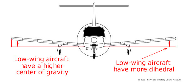
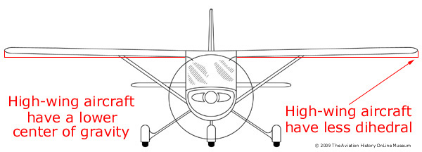
3. Vertical position relative to the fuselage (high, mid, or low wing)
4. Horizontal position relative to the fuselage
5. Cross section (or airfoil)
6. Aspect ratio (AR)
7. Taper ratio ()
8. Tip chord (Ct)
9. Root chord (Cr)
10. Mean Aerodynamic Chord (MAC or C)
11. Span (b)
12. Twist angle (or washout) (t)
13. Sweep angle ()
14. Dihedral angle ()
15. Incidence (iw) (or setting angle, set)
16. High lifting devices such as flap
17. Aileron
18. Other wing accessories

http://faculty.dwc.edu/sadraey/Chapter 5. Wing Design.pdf


In aerodynamics, the lift-to-drag ratio, or L/D ratio, is the amount of lift generated by a wing or vehicle, divided by the drag it creates by moving through the air. A higher or more favorable L/D ratio is typically one of the major goals in aircraft design; since a particular aircraft's required lift is set by its weight, delivering that lift with lower drag leads directly to better fuel economy, climb performance, and glide ratio.
The term is calculated for any particular airspeed by measuring the lift generated, then dividing by the drag at that speed. These vary with speed, so the results are typically plotted on a 2D graph. In almost all cases the graph forms a U-shape, due to the two main components of drag.
Lift-to-drag ratios are usually found using a wind tunnel

In practice, the multirole model has met with varying degrees of success over the last two decades. An example of a failure would be the MiG-23 Flogger, which never had the air superiority performance to hold its ground, just like the stillborn naval F-111B. More successful were the F-16 and F/A-18, both born as lightweight transonic dogfighters. Their limitation as bombers lay primarily in limited payload radius performance, low level ride quality for deep penetration, and initially with the F-16, limited tools for precision weapon delivery and defence penetration. The most successful example is without doubt the F-15E/I/S which has proven to be almost as good a bomber as the F-111, and improves on the counter-air lethality of the F-15C.


The now classical air superiority aerodynamic performance model is based on the idea of superior energy manoeuvrability, a concept created by the USAF's John Boyd. In this model, a fighter gains a manoeuvre advantage to fire its weapons by outclimbing, outaccelerating, outturning and outlasting its opponent in a manoeuvring engagement.

Clearly flying high energy supersonic manoeuvres will require both wing design optimisation, and plenty of gas to burn. If the supersonic drag characteristics of the wing are not well matched to this model, more thrust will be required in turn limiting persistence, especially if reheat is required to sustain such manoeuvres. Big fighters like the F-15, the evolved Su-27 and the F-22A (and the stillborn and smaller F-16E/XL) have a major advantage in this style of air combat, since the eyeball range argument for small airframes becomes irrelevent. Speed is life, and gas is speed in this game.

The critical factors for range in fast jets are the fuel fraction (a measure of fuel capacity against weight) and the aircraft's drag. A typical rule of thumb for jets is that 75% of the total drag is parasitic drag and only about 25% is lift induced drag. It follows therefore that a range advantage is held by the aircraft which has the higher fuel fraction and lower parasitic drag, factors such as SFC and cruise Mach number being constant.

The other basic aerodynamic parameter of interest is agility, basic measures of which are the combat thrust to weight ratio, and combat wing loading, both defined for an aircraft weight with a given stores load and 50% of internal fuel. Higher thrust to weight ratio translates into better climb rates, acceleration and given similar wing design, sustained turn rates. Wing loading directly affects climb rate and turning performance.

Measures of Fighter Capability

80jas1.gif
80jas2.gif
80jas3.gif
80jas8.gif
80jas9.gif
80jas10.gif

MACH Aviation Magazine - på webben
5547954604_93455631cb_b.jpg


In Europe talk was going on, with the German TKF and British EAP as starting points, for a fourth generation fighter, which in due course of time would lead to “Eurofighter 2000/Typhoon”. In France, Dassault was committed to Mirage 2000 and 4000 and was in the very early stage of Rafale-discussions. In Israel, plans for the IAI Lavi, quite similar to Gripen in fact, had set in motion, but later fell prey to the cancellation axe.

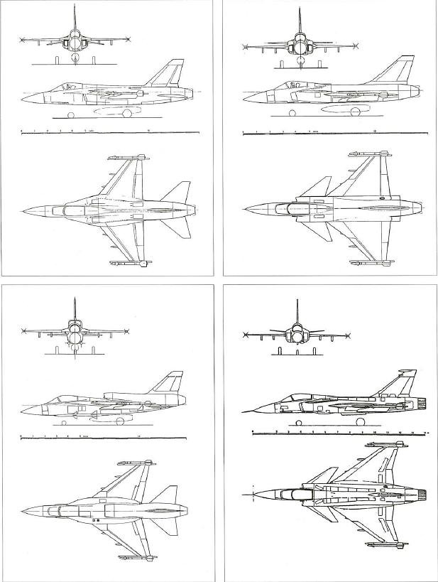
Most of these projects had one feature in common, namely the delta canard layout.

At Saab, then in the concept phase of a new fighter, this line of thinking was also the case, which is not surprising. As pioneers of this very aerodynamic shape in the sixties, and with some ten years of Swedish Air Force (RSAF) experience with AJ 37 Viggen at that time, this was quite natural. However, it did not mean that other configurations were neglected.

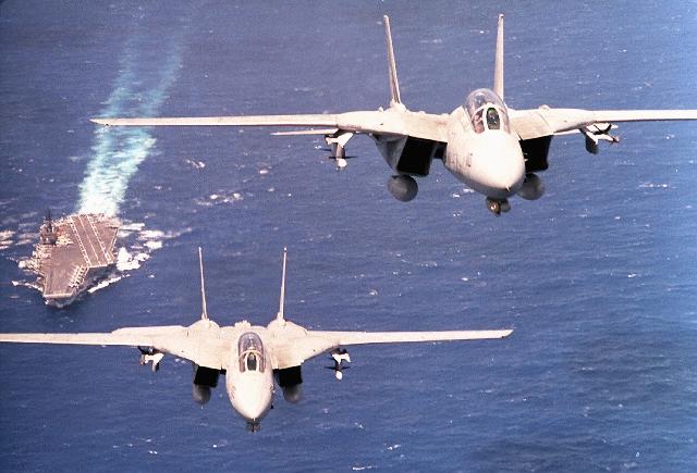
The Americans obviously intended to stay with the aft-tailed layout, as F-14, F-15, F-16, F-17/18 and F-20 could witness. It had also been reported in the press (AW&ST) that American reconnaissance satellites had caught glimpses of new advanced Soviet fighters on the tarmac of an air base: Ram-J and Ram-L they were called in the CIA jargon and subsequently they became well known as the Su-27 and MiG-29.

The choice of configuration, canard or tail, was far from obvious, initially. A substantial body of knowledge existed on the delta canard layout, gained from Viggen experience of course, but that was not entirely favourable for such a solution.

The close coupled delta canard configuration’s primary feature, its stable vortex flow up to very high angles of attack, meaning high maximum lift coefficient, had lately been realized by the Americans, instead using large strakes as forward wing root extensions together with conventional tail arrangement, as found on the F-16 and F-17/18.

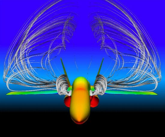
The flow physics are essentially the same. The front surface, being a delta or highly swept strake, gives off a stable detached leading edge vortex that interferes with the vortex flow from the main wing and which mutually reinforces the vortex strength of each other, and therefore burst at a much higher AOA than a lone delta wing would do. This holds true for movements in the pitch plane, but generally not for the other axis, where such flow stability is more difficult to obtain, because of asymmetrical vortex bursting, so modern fighter aircraft generally “stall” first in the lateral and directional axis.


Still the canard layout offered much, if only the weak spots could be cured. First of all a movable canard surface, higher aspect ratio wing and good cross sectional area-ruling and high slenderness ratio had to be incorporated.

Canard layout features

Engine air intake location is a topic of heated debate among aircraft designers. There are usually several options at the early design stage and pros and cons are easy to list for various arrangements. Many air inlet types were contemplated and some underwent both wind tunnel investigations and thorough studies at the drawing boards.

A fixed pitot type air intake, conventionally placed on both sides of the front fuselage, was till an easy choice, because of its simplicity and favourable cost. But everything considered, this type of intake offered most versatility. The pivots for the canards found a natural bed in this structural area and the aerodynamic carry-over loads from the canards onto the upper sides of the fuselage, acting as lift contributors, are substantial. An additional pylon location on the underside of the right intake was another bonus. This is primarily a station for various sensor pods of light weight. The left bottom side is partly occupied by the internal cannon (only for the single seater).

The aerodynamic advantages derived from the close coupled canard configuration, foremost its good vortex flow stability up to high angles of attack (AOA), that can be translated into a very high instantaneous turn rate, and which in conjunction with pivoting canards that are automatically trimmed to give optimal lift-to-drag (L/D) ratios for all cg positions, Mach and AOA, were not technically feasible for the Viggen generation of fighters. Only full span slotted flaps on the canards were present on the Viggen, for further improvement of its already excellent Short Take Off and Landing (STOL) characteristics).

One decisive feature in obtaining good, straight pitching moment characteristics from the type of plan-form was found to lie in the slightly aft sweep of the canard pivot. This was derived through an intensive wind tunnel effort that consisted of testing a formidable number of systematically differing plan-form shapes, both for the main wing and the front surfaces.

In order to successfully meet the often contradictory performance requirements stipulated by the RSAF, a good balance had to be struck between the important wing geometrical parameters, such as sweep angle, thickness, aspect ratio, twist, camber and area.

For example, a demand for high supersonic speed capability and/or low transonic buffeting levels during heavy g-loading will be eased by high wing sweep angle, but then range and manoeuvrability will be degraded accordingly. And a thin wing, good for high speed, might be a blow to rolling performance at high dynamic pressures.

The plan-form that eventually emerged was a good balance between zero-lift, wave, and induced drag and showing a maximum L/D of 9, some 25 percent and 60 percent higher than the previous Saab fighters, the Viggen and Draken respectively. Leading edge sweep angle, actually three different angles for the main wing, is higher on the canard surface to ensure stable flow, as the up-wash there can increase the local AOA substantially.

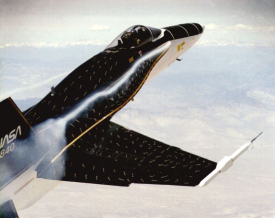
High angle of attack

The topic of air combat at high angles of attack has gained much interest since the seventies, when it made reappearance, perhaps helped by the not-so-reliable air-to-air missiles of that era. Air combat seemed to end up like a classic dog-fight, with decreasing speed and subsequent high AOA. Many early supersonic fighters had a tendency to stall out of the sky when entering this region of the flight envelope, to the dismay of its pilots, as recovery was often difficult, if not impossible.

The Viggen aircraft had gone through a program of spin testing in the late seventies, that verified the rather benign high AOA characteristics of the canard layout, a fact contrary to what was known on some contemporary aft-tailed foreign fighters. So this was also an argument favouring the Gripen canard layout. Early investigations in vertical spin tunnels and tests in different rotary rigs and subsequent simulations, also pointed to acceptable spin behaviour.

A very substantial flight test program that recently was concluded for both the single as well as the two seat Gripen versions has also fully verified the excellent recovery capability, both in manual test mode and in the normal automatic mode. There exists a requirement in the Gripen project specification for a spin recovery capability, and if this can not be shown, a spin prevention system must not allow a departure to happen. Flight testing has also verified that the EFCS matches this additional demand. Double insurance might be said to exist.

As remarked previously, the only externally visible “fix” to the airframe are a pair of small strakes behind the canard surfaces. This type of “flow augmentation system”, often serving the purpose of directional and lateral stability enhancement at high AOA, is not uncommon on fighters; suffice to mention the Eurofighter and the Mirage 2000.

A spectacular Gripen aircraft departure and ensuing crash at a public air display in 1993, was the cause of modifications and revisions to the EFCS control laws in order to cure certain ailments there, one example being pilot induced oscillations (PIO). Among the changes was one pertaining to canard deflection angles at high AOA in combat mode, to increase margins for the trailing edges surfaces to run into a geometrical limitation, and thus possible longitudinal stability loss and eventual departure.

Yaw and roll stability at high AOA is strongly dependent on canard incidence, and slightly above the MLL boundary, stability drops off rapidly, becoming unstable earlier for canard deflections in the region of minus 10 to minus 25 degrees. Obviously, this incidence range was avoided. Instead small positive values of canard deflection were used in the control law’s schedules. This was beneficial, as it meant that the trailing edge surfaces were positive, that is rear end down, thus giving more positive lift. But now it was realized that in some conditions, a physical, geometrical limitation to the elevons might be encountered, which momentarily caused loss of stability.

A low speed wind tunnel program had immediately been instigated, and for the first time the large low speed wind tunnel model’s electrical engines, that normally were used only to provide discrete incidence changes to facilitate operations, where now deflected continually during a run.

A bunch of “fixing devices” was tried, and success was instant with several of these. The earlier rapid drop of stability was now completely over-bridged, and the plots showed good, continuous behaviour, indicating at dramatic improvement of the flow characteristics in that a delay of separation occurred to slightly higher alphas. A new canard trim schedule could now be introduced that eliminated the risk of the control surfaces being limited in its travel.

The flow phenomenon, commonly called “dynamic lift”, perhaps more aptly called aerodynamic hysteresis, has been the object of intense interest in some countries for decades, not the least has this been the case in Russia. Its best public known, practical application may well be the awesome aerobatic display performed by test pilot V.G. Pugachev and his “cobra” turn in a Sukhoi Su-27.

When these hysteresis effects manifested themselves during high AOA/spin tests in the specially modified second Gripen prototype, they came as no surprise. Years prior, low speed wind tunnel tests with pitching motion of the model had already demonstrated the presence of marked unsteady flow effects, hysteresis, in the post stall alpha regime. Normal force hysteresis was most evident, but all the other components, except side force, had their share.

In the high AOA and spin tests that has taken place since 1996 and recently concluded successfully, the normal tactic was to initiate the tests with a near vertical climb with speed dropping off to near zero and a rapid increase of AOA up to extreme angles, and the aircraft could then be “parked” at 70 to 80 degrees of alpha. When giving adverse aileron input there, a flat spin with up to a maximum of 90 degrees per second of yaw rotation started and could then be stopped by pro aileron input. Recovery followed, whenever commanded.

A very recent test performed in a specially high AOA equipped twin seat Gripen version has recorded a noticeable increase in maximum normal force coefficient over the static data base value, jumping up to 3.2, nearly doubling the static number 1.8.

Wind tunnel and flight test data correspond reasonably well, but it must still be said that modelling these effects are difficult, so normally in high AOA simulations they are neglected. In the future, their inclusion will hopefully improve simulations of more complex behaviour, like departure entrance.


Aerodynamic summary

The salient points in the Gripen aerodynamics are:
Digital fly-by-wire control system and relaxed, negative static stability in pitch (cg far aft) have made the disposition of the delta canard layout, internal as well as external, much easier, whereby:

Optimal cros sectional area ruling, thus wave drag reduction, has been fully realized.

Main landing gear stowed in fuselage, therefore external stores close to cg, small cg-shift that improves flying qualities.

Wing far forward, enabling long tail cone, meaning base drag and local area distribution favourable, and efficient air brake location on tail cone with small transients when deployed.

The direct fall-out of relaxed static stability are:

· Higher trimmed lift.
· Reduced lift dependent drag.
· Reduced supersonic trim drag.

Delta canard’s inherent good aerodynamics are:

· Stable detached leading edge vortex flow, high maximum lift coefficient.
· Positive trim lift on all lifting surfaces.
· Floating canard offers stable aircraft if EFCS fails.
· Good field performance (take off and landing), enhanced by special aerodynamic breaking mode.

· Battle damage tolerance good, “overlapping” control surfaces.
· Potential for future adaptations, like steep approach, fuselage aiming.
· Low buffeting levels made even better with leading edge flaps.

Spin recovery known to be acceptable for close coupled delta canard (not necessarily so for a long coupled canard configuration):

· Proven spin recovery capability for complete cg and AOR range.
· Nor risk of being trapped in a superstall, control authority exists.


A delta wing as on the Gripen offers a light but strong and stiff structure in conjunction with the use of CFC on the outside skins and main spars, even when the relative thickness of the wing is small.

The question of stiffness is vital, as the single-spar aluminium winged Viggen had shown years before. Not initially meeting the severe requirements on roll rate at high dynamic pressures, more hydraulic cylinders for the moving of the inner trailing edge elevons had been added. And the wings broke.

Early into the Gripen project, the industry discussed the trouble that McDonnell Douglas faced in complying with US Navy roll rate demands for the F/A-18. Aileron reversal had occurred during testing of roll rate at high speed/low altitude. The rather high aspect ratio wing lacked enough stiffness and had to be strengthened, adding weight.

At Saab, an intense cooperative work between the aerodynamicists and the strength department was instituted. Flight mechanics simulations had established the required minimum values for the flex-to-rigid ratio of the rolling-moment-due-to-aileron-deflection-derivative, for meeting the very stringent supersonic roll rate demands. The British Aerospace designed CFC wing was fully up to expectations, as flight tests revealed early, allowing a high rate of roll at the critical Mach/altitude/load factor values stipulated.


A delta wing also offers a fairly large volume for fuel and has in general good static and dynamic aero-servo-elastic stability properties, even with large external stores on the wing weapons pylons.

Careful area-ruling was adhered to during the design phase, and constant improvement suggestions flowed from the aerodynamicists to the airframe design engineers. A particular case of point was the front fuselage that was of circular shape initially, but had to yield to a complicated super-elliptical geometry. Significant gains in wave drag and also high AOA behaviour, were among the pay-offs, but the manufacturing department expressed concern over escalated costs.

Airframe summary
Delta wing, multi spar, carbon fibre composite, offering large fuel volume and low weight.

Strong and stiff wing with good aeroelastic properties. High flex-to-rigid ratios for aerodynamic control derivatives.

Fuselage mounted main landing gear means good external stores capability and small cg-shift, thus easier to meet Flying Qalities requirements.

Optimal cross sectional area distribution and mid winged blended body with low drag.

-------------------------------------------------------------------
 
http://www.defence.pk/forums/milita...ts-designs-index-2nd-post-28.html#post1590554
http://www.defence.pk/forums/milita...ts-designs-index-2nd-post-26.html#post1562188


CANARDS

Modern high-speed aircraft, especially military, are very often equipped with single or compound delta wings. When such aircraft operate at high angles-of-attack, the major portion of the lift is sustained by streamwise vortices generated at the leading edges of the wing. This vortex-dominated flow field can breakdown, leading not only to loss of lift but also to adverse interactions with other airframe components such as the fin or horizontal tail

The performance of a canard design depends strongly on the amount of lift that the canard must carry. This is set by stability and trim requirements.
An analysis of the effects of canard shape, position, and deflection on the aerodynamic characteristics of two general research models having leading edge sweep angles of 25 and 50 degrees is presented. The analysis summarizes findings of three experimental transonic wind-tunnel programs and one supersonic wind-tunnel program conducted at this Center between 1970 and 1974. The analysis is based on four canard geometries varying in planform from a 60-degree delta to a 25-degree swept wing, high aspect ratio canard. The canards were tested at several positions and deflected from -10 to +10 degrees. In addition, configurations consisting of a horizontal tail and a canard with horizontal tails are analyzed. Results of the analysis indicate that the canard is effective in increasing lift and decreasing drag at Mach numbers from subsonic to high transonic speeds by delaying wing separation. The effectiveness of the canard is, however, decreased with increasing Mach number. At supersonic speeds the canard has little or no favorable effects on lift or drag. It is further shown that the horizontal tail is a superior trimming device than the close- coupled canard at low-to-moderate angles of attack and that a configuration consisting of canard, wing, and horizontal tail is superior in performance, to either canard or horizontal tail at high angles of attack.

80jas2.gif


The Canards in the Lavi have also dihedral but also they are far too close to the wings in fact over them-- The Eurofighter`s are not as close to the wings as those on the Lavi, the position has to do with drag/lift ratio, the best combination is high aspect canards low aspect wings check the Eurofighter has also strakes -- chinese J-10 also the canards are not too far from the wing, however are not so close as those in the Lavi and Rafale, both the Eurofighter and J-10 have the least drag canard delta wing configuration specially good for a fast aircraft -- the Viggen has low aspect wings and canards, these low aspect canards and wing are best configured for high lift


long-coupled canard and close-coupled canards= The two approaches to canard fighter design are more different than the names imply.
In a close-coupled design, the developers were trying to optimize the aerodynamic interaction between the wing and canard, with the objective of improving aircraft lift-to-drag and high angle-of-attack performance. For the Lavi , this means that these airplanes can fly further on less fuel than their conventional counterparts.
In a long-coupled design like the Eurofighter Typhoon or X-31, the developers were trying to minimize the canard-wing interactions, and simplify their aerodynamic design process. They still gain the benefits of improved aerodynamic control at high angles of attack, but they do not see an appreciable improvement in the airplane's lift to drag ratio.
You can tell the difference between the two approaches to canard fighter design, based on how close the canard is positioned to the airplane's wing (measured in mean chord lengths), and also by whether the canard is positioned above or below the wing. On the Lavi, J-10, Kfir, Gripen and Rafale, the canard is positioned just ahead of, and above the wing, to maximize the aerodynamic interaction between the two. On the Typhoon and X-31, the tips of the canard are canted downwards, to ensure that the canard tip vortices are swept below the wing.


Novi Avion
Novi13ot.jpg


What does mean LERX ?

It is an English abbreviation of Leading Edge Root Extension who wants literally to say : Extension of the root of the leading edges.
Word corresponding in French is: APEX.


Where are they on the plane ?

LERX are the natural prolongations of the wings towards the nose of the plane. In some kind, they make the joint between wings and fuselage.

The F-18 has LERX of very great dimensions so much so that his manufacturer, Northrop (absorbed since by Boeing), had baptized "Cobra " the preliminary projetct due to the fact that this airplane seen on top resembled the reptile with these two surfaces behind the head.

All aerodynamic surface forming an angle higher than 30˚ with the axis of relative wind passing around it stalls, because the air passing on the upper face of this part changes from a laminar flow to a turbulent flow. The turbulet airflow create a fall of lift power. The wing takes down and the
plane falls!

This phenomenon is even more delicate at low speed due to the fact that the speed of the air moving on the top surface of the wing decreases
with the proper speed of the plane. Lift obtained by the wings being directly in relation with the speed of the airflow of the upper surface of
the wings, when the plane slows down, the lift power decreases.

It is possible to counter this phenomenon by 3 main ways:

- To increase speed obviously, but it's not what one seeks at the time of the landing for example...
- To increase the angle which the wing and the airflow are forming, this one being limited to 30˚ as we saw above.
- To increase camber of the wing. It is what we do when the plane extends the flaps and the mobile leading edges at the time
of landing or takeoff.

Militarily speaking, it is interesting for a fighter, involved in a dogfight for example, to decrease its speed as much as possible in order to let
a faster airplane go ahead. By this manoeuvre, the fastest plane of both go ahead of its adversary and then allows the slower airplane
stay behind him in position of shooting.

It is vital for the fighters to fly fast to be able to reach a zone of intervention as soon as possible, but it is critical too to be able to fly as slow
as possible while keeping the plane control in order to be able to ensure itself to remain behind the adversary and therefore in offensive
position.

In that way, the LERX provide a considerable supplement of lift at raised angles of attack, i.e. when the angle formed by the wings and the
relative wind direction due to the displacement of the plane increases.
Indeed, the LERX generate powerful swirls of air or Vortex which increase the air velocity on the roots of wings and around tails. This makes
it possible to keep the control of the plane at angles superiors of 30˚. These Vortices when are intenses are particularly visible,
materialized by the condensation of the moisture of air.

LERX also allow the correct air feeding of the engines during those flights at high angles.
Lerx

http://dc185.*******.com/img/eWV16wOM/0.9003554746114637/check1.JPGhttp://dc185.*******.com/img/MfX6oRPR/0.44802734121847665/check2.jpghttp://dc185.*******.com/img/tAXxr7qS/0.45726369516279997/check3.JPG
dfJJL.jpg
xEYxD.jpg
 
f18-lex-cfd1.jpg
f18-lex-cfd2.jpg

CFD visualization of vortices created by leading edge extensions on the F-18
f18_46.jpg

Vortex bursting observed during smoke flow visualization tests on NASA's F-18 HARV
Aerospaceweb.org | Ask Us - F-18 Leading Edge Extension Fences


militairefc1274.jpg
Xovzj.jpg


Condensation vortex flows along an F/A-18's LERX
Leading edge root extensions (LERX) are small fillets, typically roughly triangular in shape, running forward from the leading edge of the wing root to a point along the fuselage. These are often called simply leading edge extensions (LEX), although they are not the only kind. To avoid ambiguity, this article uses the term LERX.

On a modern fighter aircraft they provide usable airflow over the wing at high angles of attack, so delaying the stall and consequent loss of lift. In cruising flight the effect of the LERX is minimal. However at high angles of attack, as often encountered in a dog fight, the LERX generates a high-speed vortex that attaches to the top of the wing. The vortex action maintains a smooth airflow over the wing surface well past the normal stall point at which the airflow would otherwise break up, thus sustaining lift at very high angles.

LERX were first used on the Northrop F-5 "Freedom fighter" which flew in 1959,[1] and have since become commonplace on many combat aircraft. The F/A-18 Hornet has especially large examples, as does the Sukhoi Su-27. The Su-27 LERX help to make some advanced maneuvers possible, such as the Pugachev's Cobra, the Cobra Turn and the Kulbit.
 
Wingtip shape

Little information on this difficult area has been published, though the curved tip received a good deal of British attention in the 1960s. The aim is constant isobar sweep across the span to reduce transonic wave drag. As noted in Chapter 3, an indented fuselage can be used to reduce the loss of isobar sweep at the wing/body junction. A similar tendency of the isobars to reduce their sweep is encountered at the wingtips. This can be suppressed by locally increasing the wing's leading-edge sweep at the tip. a solution to be found on the BAe Harrier, Hawk and EAP.
Another notable wingtip shape is the raked lip, featured on the F-15. Flight tests on early versions with streamwise tips showed higher-than-predicted wing-root bending moments, caused by the outer wing panels producing more lift than expected. This reduced the safety strength margins and threatened a reduction in fatigue life. Heavy buffet and excessive Dutch roll were also encountered. The problem was solved by removing 0.46 m2 of wingtip on each side, giving an increased flutter margin. One benefit of straight tips is their ability to carry launcher rails for light air-to-air guided weapons, as on the Mirage F.I, F-16, F-18 and Rafale. This helps satisfy the demand for increased ordnance loads. Furthermore, careful design of the wing/launcher region has yielded worthwhile improvements in wing L/D.


Disadvantages of the delta

By the 1960s the disadvantages of the delta wing planform had begun to make themselves felt as the demand grew for the lifting of larger weapon loads off shorter runways and for greater air combat manoeuvrability. The swept wing had by this time shown itself to be the more versatile, and most designers had dropped the delta. Indeed, even Dassault, the leading exponent of the delta, rejected it when developing an aircraft with reduced landing speeds, improved manoeuvrability and heavier weapon load. This was the Mirage F.I. which, with a swept wing two-thirds the area of that of the Mirage III and only 9kN more thrust, is faster, can loiter subsonically and pursue supersonically for three times as long, can carry much more offensive load over almost twice the distance, is 80% more manoeuvrable and lands 20% slower.
1 With its high leading-edge sweep and very low aspect ratio, the delta is less efficient as a lifting planform. The low lift-curve slope means that it must be flown at much higher angles of attack to generate the same lift. However, the demands of tail clearance and pilot view limit the usable AOA, as shown in Fig 37. Furthermore, the delta is unable to use trailing-edge flaps unless it has a separate tail to trim out the large nose-down pitching moment. These factors combine to give tailless deltas very high landing speeds and poor airfield performance.
2 The delta's high span loading (W/b) results in very high lift-induced drag in subsonic flight. This is a critical drawback in air combat, since very high thrust must be available to avoid a severe drop-off in specific excess power. This is further compounded in manoeuvring by the large trimmed lift loss and associated drag arising from the increasing downloads on the trailing-edge controls as AOA is increased (Fig 44).
3 The low wing loading of the early deltas made them very sensitive to gusts in low-level high-speed flight. This was overcome on the TSR.2 by using, together with a low tail, a very small delta wing of only 65 m2 area with blown flaps and a high thrust/weight ratio. Low-speed manoeuvrability is however invariably compromised whenever high wing loadings (i.e. greater than 500kg/m2) are used on deltas.
4 Supersonic manoeuvrability is greatly restricted by the relative ineffectiveness of the delta's trailing-edge controls, known as elevons (elevators/ailerons), compared with separate tail surfaces. In addition, the aft movement of the aerodynamic centre during transonic acceleration, though reduced by the use of high sweep, is still large in actual distance though appearing small in terms of chord length. Allied to the restricted allowable range of centre-of-gravity position arising from the limited trimming power of the elevons, this means that trim drag is high. An up-elevon deflection is needed to produce the restoring download.
Restricted CG range was a problem with the Convair B-58, in which fuel had to be transferred internally in order to maintain the CG near the aft limit throughout the flight, partly to minimise supersonic trim drag. The elevon deflection required for rotation and lift-off at maximum weight was less than –5°, due to the aft CG and the low-slung engines. In supersonic flight at altitude, however, the elevons were never at less than –5°.
In Mach 3 cruise the Lockheed SR-71 minimises its trim drag by pumping fuel aft to shift its centre of gravity. In addition, the forebody chines (see Chapter 4) locate the aerodynamic centre well forward.
5 The combination of high wing sweep and the large AOAs necessary for high lift means that the effective dihedral (i.e. rolling moment due to sideslip) can be excessively high at low speed. Thus if a small dihedral effect is achieved at high speed, then the effective dihedral at low speed or high lift, or even high speed at high altitude, disturbs the desired relationship between lateral and directional stability. Dutch roll may then become exaggerated, requiring low-mounted wings and yaw dampers to move the rudder in opposition to the yawing motion. The YF-12, with its 60° leading-edge sweep and high dihedral effect, has approximately zero wing lift when its nosewheel is in contact with the runway during take-off, in order to minimise cross wind e fleets.
6 Longitudinal (i.e. pitch) damping cannot be as high as for a conventional tailled configuration. Typical resulting problems include the pilot-induced oscillations suffered by the Saab Draken, ultimately remedied by the use of automatic pitch dampers.
Although the addition of a tailplane to a delta would appear to improve longitudinal control and pitch damping, it is in fact the tailplane's vertical position which is all-important. A high-mounted tailplane may improve matters only within the low-AOA pitching envelope, which isn't that troublesome anyway. But at high AOA the separated flow from the wing may actually make a high tailplane destabilising. Aeroelastic problems can also arise from mounting a tailplane on top of a very thin {58} vertical stabiliser. For these reasons all the successful tailled deltas — outstanding examples are the MiG-21 and Su-21 — have featured low-mounted tailplanes.


----
Though the simple delta is in itself a poor choice for the air-superiority role, developments like those incorporated in the Mirage 2000 have transformed this planform into a leading contender. In the early 1980s designs for compound-sweep deltas coupled with foreplanes began to appear in Europe as the next generation of air combat aircraft was defined. Two projects in particular feature compound-sweep wings: the BAe/MBB/Aeritalia ACA now the European Fighter Aircraft (EFA), and the Dassault-Breguet ACX, now named Rafale. The inboard and outboard sweep angles were originally 60°/40° and 55/42° respectively. The high degree of inboard sweep promotes strong vortex formation at high AOA, and low wave drag at supersonic speed. The lower sweep of the outboard panels maximise manoeuvrability by lowering the span loading to reduce the induced drag which has been the drawback of simple deltas. Both projects were designed with automatic leading-edge slats, those on the outboard panels being particularly powerful as a result of the lower sweep. The British precursor for EFA, the Experimental Aircraft Programme (EAP), has subsequently appeared with a curved inner leading-edge panel to further promote vortex formation and to improve the area distribution. Nevertheless, the EFA wing is likely to have a straight leading edge with 53% sweep.
Despite industry's apparent universal enthusiasm for the canard-delta configuration, some {63} analysts asserted that it had no inherent advantages over the traditional aft-tail configuration. Specifically, the critics contended that the canard configuration is more critical in the area of high-AOA pitch-up problems and lateral/directional stability.


Vortex lift

Then, in the mid-1960s, Northrop began work on improving the manoeuvrability of its F-5. The company had been the leading exponent of the art of combining moderate sweep and low taper to achieve good flow characteristics and spin resistance, as typified by the T-38 supersonic trainer. When the F-5A appeared in 1963 it differed from the T-38 in having a very small leading-edge extension (LEX), intended basically to alter the cross-sectional distribution and so reduce wave drag for maximum transonic acceleration. The Northrop designers were aware of the vortices that the LEX would produce and the induced-drag penalty that would result. However, not only was the wave drag reduced, but a 10% increase in usable lift appeared at high AOA (see Fig 82), which markedly improved turning performance. The size of the LEX on the F-5E was increased to 4.4% of the basic wing area when the intakes were extended forward. This further improved the area ruling (see The Area Rule, page 53) and, more important {90} still, increased the maximum lift by 38%. Further development of the F-5E has led to the F-20. which, with increased LEX area and higher thrust/weight, has a 25%-higher sustained turn rate. Both aircraft have instantaneous turn rates comparable with that of the F-15, which achieves 14°/sec at Mach 0.9 at 4,500m, mainly by virtue of its much lower wing loading.
Impressive though the above figures are, the greatest advance in the application of vortex lift to combat aircraft came in 1966, when Northrop began work on the F-5 derivative which became the YF-17 and. ultimately, the F-18. As shown in Fig 83. the basic YF-17 wing planform already displayed the virtues of the classic moderately swept wing (i.e. low induced drag, good stability characteristics, and high spin-resistance). Us combination with a much larger LEX turned it into a truly hybrid wing, with the LEX generating a very strong vortex field not only on itself but also on the parent wing. The maximum lift capability of the hybrid wing is shown in Fig 84, which reveals a 50% increase in lift at subsonic speed for just 10% more wing area. {91}
On the debit side, the separated nature of vortex flow results in a loss of leading-edge thrust, leading to increased drag at low AOA. As shown in Fig 85. however, this can be rectified by the use of manoeuvre flaps. The combination of LEX and manoeuvre devices produces very large drag reductions at typical manoeuvring AOA, giving an improvement of as much as 25% in sustained turn rate. In addition, aileron effectiveness is maintained up to much higher AOA, as shown in Fig 86.

pyjNv.jpg


Other advantages of LEX include reduced AOA at the under-strake air intakes (see Chapter 2) and reduced transonic aerodynamic centre shift, giving lower supersonic trim drag at high g. In its test programme the YF-17 demonstrated a far wider range of flying attitudes than had ever before been attained by a comparable aircraft: designed to remain fully controllable up to 45° AOA, it was in fact flown to 63° without showing any sign of departure tendencies. It also achieved a manoeuvre combining sideslip and AOA of 36° and 40° respectively.


Compound-sweep deltas

Then, in mid-1980, the USAF defined a more immediate requirement for an improved ground attack aircraft to succeed the F-4 and F-111. General Dynamics shifted its sights to this goal and changed certain details of its cranked-arrow wing to meet the new requirement. The changes affected the camber, twist and trailing-edge reflex, optimising the wing for supersonic speed at low level. Remarkably, the new wing was not part of a completely new aircraft but was married to the existing F-16. As can be seen in Fig 46, the transformation was profound. The new 60m2 wing was mated to the basic F-16 structure by means of two fuselage plugs, one 0.91 m long and inserted ahead of the undercarriage, and a 0.67 m section aft. To provide for ground clearance on rotation the longer rear fuselage was angled up by 3° and the ventral fins deleted. The upsweep puts the thrust line below the CG, helping to improve rotation on takeoff. This, together with the very advanced wing, allowed the F-16XL (subsequently known as the F-16E) to be rotated at speeds down to 195km/hr, leading to a field-length requirement only two-thirds that of the F-16A. Flight testing of the F-16E showed it to have a lift/drag ratio between 10 and 45% better than that of the basic F-16A, and it could roll and pitch faster in any configuration. It could also pull an AFCS-limited 9g over twice the Mach-number range. While the F-16E offers no L/D improvement in subsonic manoeuvres, it does retain the subsonic cruise efficiency of the F-16 planform. Where it scores is in supersonic cruise performance: at Mach 2.2 its L/D is over 9. This is due to the improved fineness ratio arising from the increased fuselage length and even better wing/body blending. Even though the wing area is more than double that of the standard F-16, the skin friction drag is only 22% more, due partly to the deletion of the horizontal tail.
The cranked-arrow planform of the F-16E comprises a sharply swept (70°) leading-edge inboard section lying within the shock cone of the nose and, at 63% semi-span, a 50° outboard section of thin profile and sharp leading edge. This is designed to obtain the low wave drag associated with highly swept or thin wings without the aerodynamic penalties of sweep or structural problems of thin sections. However, the F-16E takes the delta planform {61} much further in that the experience gained with the leading-edge strakes of the basin F-16 enabled General Dynamics to maximise the vortex-lift benefit. The two swept panels of the cranked-arrow planform produce vortex systems which mutually interfere. At low angles of attack the leading-edge vortex from the inboard wing passes over the root chord of the outboard wing panel. In addition, vortex lift is available at the tip as a result of the action of the outboard leading-edge vortex. At high AOA the single primary vortex system acts over the whole of the outer panel. Thus augmented vortex lift occurs at supersonic speed, while at lower speeds the benefits of the primary vortex counter the high induced drag which plagued earlier delta planforms.

The improvements in stability and control with and without stores were such that no limitations due to buffet, wing rock or nose slice, nor spin tendency were encountered during the flight test programme. Angle-of-attack excursions resulted when the airspeed dropped to zero but the aircraft always recovered without any pilot input. 360° rolls at maximum g/maximum AOA similarly failed to cause any departure from controlled flight (Fig 47).
The major difference between the application of vortex flow to transonic fighters (e.g. F-16, F-18) and to the supercruise fighter (e.g. F-16E) is the extent of vortex lift available. The supercruise fighter, having more of the wing highly swept, develops more of this lift. Only a small fraction of the increased lift comes from the potential (or attached-flow) lift; the rest is due to the vortex lift acting over the increased wing area. This extra lift increases instantaneous turn rate, now regarded as more important than sustained turn rate, which largely governed the original F-16 design. Newer gunsights and missiles like the AIM-9L Sidewinder reduce the need to hold the target in the sight for weapon aiming. General Dynamics relinquished a small amount of sustained manoeuvrability in order to double the 9g envelope and move it into the high supersonic regime.
It should not however be forgotten that the F-16E was initially developed for ground attack. In this respect the new wing increased internal fuel capacity by 82%, which eliminated for most missions the weight and drag of external tanks. This gave it a 45% increase in combat radius with twice the weapon load of the F-16A and a more than 120% increase with the same weapon load. The aircraft is equipped with 17 store stations with 29 hard-points. In the event the F-15E, a development of the two-seat F-15C was chosen as the dual-role fighter for the USAF, though it remains possible that development of the F-16E will continue.

fig046.gif

http://scilib.narod.ru/Avia/DAC/dac.htm

gBHoO.png

EpTud.gif
70UQ8.jpg

http://www.mig-21.de/english/technicaldataversions.htm
 
FltControlSfces.gif

TH20G6.jpg


Two very different area wings can provide the same lift by flying at different angles of attack (and hence different lift coefficients). This is a big reason why aerodynamicists tend to work in coefficients rather than absolute forces.
Since weight is usually an input, the lift is constant. So more area means less lift coefficient (same lift), and lower drag.
Sweep, span, and area are all totally independent.
Wingspan
Aer.lingus.a320-200.ei-cva.planform.arp.jpg


Wing loading
In aerodynamics, wing loading is the loaded weight of the aircraft divided by the area of the wing.[1] The faster an aircraft flies, the more lift is produced by each unit area of wing, so a smaller wing can carry the same weight in level flight, operating at a higher wing loading. Correspondingly, the landing and take-off speeds will be higher. The high wing loading also decreases maneuverability. The same constraints apply to birds and bats.

Wing loading is a useful measure of the general maneuvering performance of an aircraft. Wings generate lift owing to the motion of air over the wing surface. Larger wings move more air, so an aircraft with a large wing area relative to its mass (i.e., low wing loading) will have more lift at any given speed. Therefore, an aircraft with lower wing loading will be able to take-off and land at a lower speed (or be able to take off with a greater load). It will also be able to turn faster.


Fuselage lift
The F-15E Strike Eagle has a large relatively lightly loaded wing

A blended wing-fuselage design such as that found on the F-16 Fighting Falcon or MiG-29 Fulcrum helps to reduce wing loading; in such a design the fuselage generates aerodynamic lift, thus improving wing loading while maintaining high performance.
[edit] Variable-sweep wing

Aircraft like the F-14 Tomcat and the Panavia Tornado employ variable-sweep wings. As their wing area varies in flight so does the wing loading (although this is not the only benefit). In the forward position takeoff and landing performance is greatly improved.[11]
[edit] Fowler flaps

The use of Fowler flaps increases the wing area, decreasing the wing loading which allows slower landing approach speeds.


http://dc306.*******.com/img/s8-jwhsT/0.6235182629976099/gra6.PNGhttp://dc317.*******.com/img/gyg_jEpA/wing_configurations.PNG

canardvstailhc5.jpg


Aerodynamic Characteristics

Perfection in airframe performance can give the pilot battle-winning edge, providing that airframe is part of the Eurofighter Typhoon Weapon System.

Eurofighter Typhoon has a foreplane/delta configuration which is, by nature, aerodynamically unstable.

The instability of the aircraft is derived from the position of a theoretical “pressure point” on the longitudinal axis of the aircraft. This is calculated from the contribution to lift from each of the aircraft components (the wings, the canards, fuselage etc). If the pressure point is in front of the centre of gravity on the longitudinal axis, the aircraft is aerodynamically unstable and it is impossible for a human to control it.

With the Eurofighter Typhoon, in subsonic flight the pressure point lies in front of the centre of gravity, therefore making the aircraft aerodynamically unstable, and is why Eurofighter Typhoon has such a complex Flight Control System – computers react quicker than a pilot.

When Eurofighter Typhoon crosses into supersonic flight, the pressure point moves behind the centre of gravity, giving a stable aircraft.

The advantages of an intentionally unstable design over that of a stable arrangement include greater agility – particularly at subsonic speeds - reduced drag, and an overall increase in lift (also enhancing STOL performance).
http://www.eurofighter.com/capabilities/performance/aerodynamic-characteristics.html


http://books.google.com.pk/books?id...sign and centre of gravity of fighter&f=false

Fundamentals of Airplane Flight Mechanics
*By David G. Hull


detailed diagrams / comparative pics of different fighter programmes are posted here
http://www.defence.pk/forums/air-warfare/75408-combat-aircraft-projects-designs-index-2nd-post.html
 
I wasnt planning to start a thread... was just surfing for info on lift-to-drag ratio --- ended up starting a thread on it...from lift-to-drag ratio of different fighters , this thread is growing out to be a designs & aerodynamics thread... maybe will change title

trying to make an informative thread... will appreciate input
:cheers:
 
tWsYt.jpg


Wing loading
In aerodynamics, wing loading is the loaded weight of the aircraft divided by the area of the wing.[1] The faster an aircraft flies, the more lift is produced by each unit area of wing, so a smaller wing can carry the same weight in level flight, operating at a higher wing loading. Correspondingly, the landing and take-off speeds will be higher. The high wing loading also decreases maneuverability. The same constraints apply to winged biological organisms


Aspect ratio (wing)
In aerodynamics, the aspect ratio of a wing is essentially the ratio of its length to its breadth (chord). A high aspect ratio indicates long, narrow wings, whereas a low aspect ratio indicates short, stubby wings ----Maneuverability: a high aspect-ratio wing will have a lower roll rate than one of low aspect ratio, because in a high-aspect-ratio wing, an equal amount of wing movement due to aileron deflection (at the aileron) will result in less rolling action on the fuselage due to the greater length between the aileron and the fuselage. A higher aspect ratio wing will also have a higher moment of inertia to overcome. Due to the lower roll rates, high aspect ratio wings are usually not used on fighter aircraft.
Geometry Definitions


Wing Dihedral is the upward angle of an aircraft's wing, from the wing root to the wing tip. The amount of dihedral determines the amount of inherent stability along the roll axis. Although an increase of dihedral will increase inherent stability, it will also decrease lift, increase drag, and decreased the axial roll rate. As roll stability is increased, an aircraft will naturally return to its original position if it is subject to a brief or slight roll displacement. Most large airliner wings are designed with dihedral.

On low-wing aircraft, the center of gravity is above the wing and roll stablity is less pronounced. This factor requires the use of greater dihedral angles in low-wing airplanes.

piper-2b.jpg


On high-wing aircraft, the center of gravity is below the wing, so less dihedral is required.

cessna-1a.jpg


On low-wing aircraft with wing dihedral, when a wing rolls downward, the relative wind on the descending wing becomes a component of the forward motion of the airplane and the downward motion of the wing. This produces a higher angle of attack on the descending wing and consequently more lift.
piper-2a.jpg


Highly maneuverable fighter planes have no dihedral and some fighter aircraft have the wing tips lower than the roots, giving the aircraft a high roll rate. A negative dihedral angle is called anhedral. The AV-8B Harrier II has a negative dihedral or anhedral

av8b-1a.jpg

Wing Dihedral

Large aircraft such as An-225 and C-5 Galaxy (high wing aircraft) have anhedral to reduce maneuverability, and to stabilize the aircraft. While Harrier has anhedral to increase maneuverability .

For low wing aircraft, such as commercial jets, dihedral is used to increase stability of the aircraft. As seen in the A380 image below.

A380_On_Ground.JPG


So, in military aircraft zero dihedral or negative dihedral (anhedral) is used, to increase maneuverability, while positive dihedral is used in large aircraft to decrease maneuverability.
 
F-15B Active- With Carnards and Thrust vectoring

378755main_EC96-43780-1.jpg


In 1993 Dryden Flight Research Center acquired the first F-15B (two-seat) aircraft built, following it’s career with McDonnell Douglas and the U.S. Air Force. By that time the aircraft had already undergone considerable modification, including the addition of canards and a pair of “pitch-yaw balance beam nozzles” (PYBBN) for thrust vectoring. The exhaust nozzles deflected as much as 20 degrees in a 360 degree arc.
 
Tailless delta was something the US and the Russians abandoned early. Problem with a tailless delta is that you have two wing control surfaces doubling as ailerons (roll control) and elevators (pitch control).

FBW can only do so far with delta designs. The best it can do is to prevent the pilot from pulling the plane into an angle of attack that is too excessive, keeping the AoA at the edge of threshold. Beyond that, the plane would lose both speed and lift. Even with experience, the pilot cannot not mentally compute everytime for all the speed, altitude and other factors, especially during combat.

The Mirage 2000 has an unstable profile and low wing loading which give it good instantaneous turn ability, but not sustained turning ability. Once you go turning deeper into a circle or continue to maneuver after successive maneuvers, the plane easily loses bleeds speed. Again that is due to the unassisted delta wings. This is something rectified with canards, double delta or cranked delta designs. The Mirage 2000 does have variable camber (leading edge automatic slats) in the front of the wings, which improves lift at lower speeds and reduces edge wise bleed of the airflow. So the effects are somewhat offset. Still nothing beats vortice generation flowing on top of the wings, which you can have with a canard, LERX or double delta.

One thing I might add is that some delta designs like the Mirage III and 2000 have very low wing loading which enables them to instantaneously turn quickly. The F-102 Delta Dagger and the F-106 Delta Dart also has similar characteristics. Despite the similarity of the Delta Dagger and the Delta Dart, the wings are completely different; the Dagger uses outboard wing fences, the Dart uses a more modern leading edge slats.

However, the delta quickly gathers drag in the middle of the turn as it gains alpha, so it bleeds speed and lift. Thus it is not good for sustained turn rate. When Boyd's theories came to the fore in the USAF, it placed more emphasis in sustained turn performance. Somehow the French didn't get the message as quickly, leading to the Mirage 2000.

I gather the J-8I and J-8II should perform similarly with their low wing loading. It can do one or two quick turns before air speed drops off.

As the deltas are clipped in the J-8I/J-8II I suspect the plane has a fast roll, but because of the plane's length might have some potential yaw problems. The J-8II's larger ventral stabilizer and large tail seems like a better counter to that.

Low wing loading makes a plane buffet at low altitudes. Thus, the flight of such low wing loading jets are much better at high altitudes.

The MiG-21 evolved from a low wing loading jet in its early version to a high wing loading plane in the last versions. During its evolution it picked up power and weight, but the wings remained the same. In the case of a plane like the MiG-21bis, the instantaneous turn rate would suffer at higher altitudes but at lower altitudes, the plane is more stable and has a smoother ride. As you might suspect, planes that have a ground attack role is better to have a higher wing loading to get a smoother flight in low altitudes.

The J-7s except for the MiG-21MF based J-7C and -D, retain the original design of the MiG-21, and thus the wing loading remains nearly the same as the original. The J-7E gained some weight but did add more wing area to it so it all evens out.

With lower wing loading, you get more lift for the same speed and that translates to better maneuverability. This lift becomes more precious at higher altitudes and low wing loading is a necessity for planes performing at higher altitudes.

A higher wing loading on the other hand smooths out the plane's ride, and that helps in situations like dives, or flying in low altitudes preparing for a bomb run. A true multirole aircraft has to find a proper balance between these two attributes.

Note fighters from World War II.

Spitfire and Zero both have low wing loading. They are very agile, and can quickly turn in tight circles. Other planes falling into this category are Russian fighters like the LaGG and Yakolev series, and just about every Japanese fighter except for the Shoki.

Fighters like the Me-109, FW-190 and the P-47 Thunderbolt have high wing loading. They can dive extremely fast and deliver accurate ground attacks. Other fighters along this line are the P-36 Airacobras and the P-40 Warhawks.


MiG-21 was also designed as a high speed interceptor. When the MiG-21 was being designed, there was already a fundamental shift in airpower from the basic concept of air superiority through fighter vs. fighter engagment to the priority of intercepting high altitude nuke armed bombers. The MiG-21 just didn't let go of its dogfighter roots as quick as other interceptor designs did. One can say that the sixties was the golden age of interceptors---every design one way or another had to intercept bombers.

When you have an acute sweep delta like the MiG-21 or J-8 has, the moment these wings start getting into a turn and gaining more alpha, drag becomes higher than a sweep wing, and plane quickly bleeds speed. In a way its actually regressed in maneuverability compared to the MiG-19, which not only has a higher TWR than the Fishbed, but keeps more of its energy better in a turn. And so, an entire generation of aircraft was developed (F-4 Phantom, Mirage III, MiG-21) that turned out wasn't any better than its predecessors in WVR combat, but even inferior in some aspect.

What turned this around was the F-16. It wasn't just the Boyd theory, or the high thrust to weight ratio, or the FBW. Its main aerodynamic feature was the LERXes that force vortex generation across the wings at angle of attack. These vortices renenergize the air stream over the wings, which goes on to stabilize the wing at high alpha and reduce energy bleed. The FBW goes further to make sure no matter how much the stick is pulled back, the angle of attack would never reach to the point where the wings would generate more drag than lift, and the plane bleeds both speed and altitude.

The MiG-29 has LERXes so the Russians understood the first part of this lesson. But it would take the Su-27 before the Russians complete the second part. The Chinese certainly understood this concept of vortice generation but went about it in another way. This was how the double delta wing for the J-7E was developed.
But to take it beyond double delta and LERXes, you would need a variable and controllable surface that would serve as the vortice generator. And this led to the canard, and to the J-10.

Among the high speed interceptors, I would put the J-8II fitting in the niche between a super heavy weight like the MiG-25, and the light and lithe like the F-104 Starfighter.

I don't see the point between the FC-1 being compared to the J-8II. The FC-1 was designed as a much more maneuverable plane, better in low altitudes, while the J-8II was a strictly high speed, high sky fighter. I believe the J-8II using the WP-13B or WP-14 Kunlun engines will have a higher thrust to weight ratio, but it will only be like 10% or so.

credits to the great crobato
 
original post by Gambit


One of the many jaw dropping and simply stupidest arguments for the J-20 being propagated on the Internet by the J-20's supporters is the assertion that the F-22's rudder system is 'less advanced' than the J-20's all moving vertical stabilators.

First...There is a difference between a 'stabilator' and a 'rudder' but in short, the stabilator contains the rudder. To put it another way, the rudder is an integral and a moving part of the vertical stab to effect yaw control. If the vertical stab is designed to be all moving, then there is no rudder, the whole flight control surface act to effect yaw control. But if the trailing edge of the vertical stab is moving, then we have a 'rudder system' where there is a large main stabilizing control surface holding a smaller movable segment of the trailing edge.

Second...Structurally and mechanically speaking, there are no gross degrees of differences between the rudder and the all-moving rear horizontal stabs. We could mentally 'rotate' the entire tailplane section to make one of the rear horizontal stabs to be the all-moving vertical stab.

So is there any valid technical foundation upon which that anyonce can stand and make such an assertion? Absolutely none. The aviation historical record simply cannot be more clear about the stupidity of this assertion.

The F-117 has all-moving vertical stabs and this is publicly available information...

Lockheed F-117A Stealth Fighter
The F-117A uses fully movable V-tail surfaces and split full span trailing edge flaps.

The SR-71 has all-moving vertical stabs and this is publicly available information...

http://www.hq.nasa.gov/pao/History/x-33/sr71-faq.html
Aerodynamic control surfaces consist of all-moving vertical tail surfaces above each engine nacelle, ailerons on the outer wings, and elevators on the trailing edges between the engine exhaust nozzles.

The A-5 Vigilante has an all-moving vertical stab and this is publicly available information...

The North American A-5/RA-5 Vigilante
The Vigilante was long and sleek, with a relatively small high-mounted swept-back wing, and all-moving slab tailplanes and tailfin.

Going back further into aviation history, even the WW I German Fokker DVII has an all-moving vertical stab and this is also publicly available information...

Factsheets : Fokker D. VII

So the aviation historical record is clear that an all-moving vertical stabilator to act as both yaw axis stabilizer and control is not something recently innovated by Chinese aviation. Then what could explain the reason why does the F-15, F-16, F-22 or any other high performance military jet fighters uses the rudder system instead of an all-moving stab when its application is well known and established since the early days of aviation.

The hint is in the A-5 source above and quoted below...

North American had considered twin tailfins to meet the height restrictions of a carrier hangar deck, but although such a configuration is common now, it was too bold for the Navy at the time. North American went with a single tall tailfin that folded to one side.

A flight control element's real estate, shape, sweep angle, and effectively all aspects of its design simply cannot be put on paper and call it good. It must be precisely calculated based upon technical and human requirements. Sometimes one side will trump the other. Sometimes a compromise can be reached where the best level of each requirement is met but not its whole.

North American had designed the A-5's twin vertical stabs to be of X real estate, Y shape, and Z sweep angle -- to simplify this explanation considerably. But the US Navy needed the aircraft to be stowable below deck and such a twin tailed configuration was too radical at the time for the Navy's comfort. So in order to satisfy the Navy's human demands and to balance those demands against the technical need for effective yaw axis control, North American had to make a large single all-moving vertical stab that also fold to one side so the aircraft can be stowed below deck. The real estate of this single large all-movable vertical stab roughly equal to the original twin smaller vertical stabs for yaw axis stabilization. The all-movable feature would have the same effective yaw control as with the original twin rudders design. It was innovative but hardly inventive. It was innovative because it satisfy competing interests to high degrees while using existing knowledge and technology.

We know from established 'stealth' planforming that a single vertical stab would be detrimental towards low radar observability. That mean for the J-20 and the F-22, both must have twin canted vertical stabs. The reason why the J-20 needed both its vertical stabs to be all-moving whereas the F-22 does not is because of different flight control philosophies and demands based upon the overall design. The J-20's twin vertical stabs are smaller in real estate in comparison to the F-22 is from aerodynamic requirements. Any radar low observability benefit is incidental -- not intentional. Canting them to remove large 90deg corner reflectors is intentional.

f-22_be2.jpg


The above illustration is of today's F-22 and WW I British BE2. The BE2's all-movable vertical stab is obvious from the F-22's rudders.

If there is a credible third party technical analysis that said the rudder system is 'less advanced' than the all-movable vertical stab, regardless of era, the readers, especially those in the aviation engineering community, would greatly benefit from this information. This is not 'classified' information by any stretch of the definition. The physics would have been well known, that is IF such an inferiority exist, under what conditions, and how is that inferiority manifested in flight, especially under air combat maneuvers.

In summary, there is nothing inventive and innovative about the J-20's twin canted all-movable vertical stabs. If the F-15 or F-22 does not have all-movable vertical stabs, it is because they do not need them, not because they are somehow design 'flawed' or 'less advanced' as asserted by the J-20's supporters. Given the fact that these are publicly available information, it can only be intellectual dishonesty among the J-20's crowd that compelled the dissemination of this gross technical error.

http://www.defence.pk/forums/chines...rcraft-updates-discussions-2.html#post1824495
 
800px-Chrislea_ch3_superace_series2_g-akuw_arp.jpg
Columbine_III_aircraft.png


vortex will generate lift , high AoA --

twin tails might give stability [directional control?]...Having two vertical stabilizers allow each of them to be smaller than a single one, would decrease height in hangers-->reduction of the load at the root

The LERX were designed in to keep airflow attached at high alpha .Strakes wereadded to the LERX to stabilise the vortex

I read somewhere that twin tails reduced supersonic drag and saved structural weight -- at subsonic Mach the two fins interfere with each other, which reduces their effectiveness as lifting surfaces--At a supersonic speed, the 2 surfaces begin to work independently --twin tail fins helps the airplane benefit from this vortex and retain yaw control in high AoA--- if one engine fails , 2 vertical tails would be better in controlling the fighter --shedding vortices from the wing root , vortices being shed by the strakes are used to energise airflow over twin fins thus retaining control

my understanding [layman] is high vortex--high aoa but high drag ----> this drag can be reduced by twin tails

Drag reduction, combine the tasks of the elevators and rudder,increase surface area without increasing aspect ratio are other things that ive read regarding Vtails like on f117


the two vertical stabilizers on the F-22 Raptor angled sort of like a V-Tail as opposed to being completely vertical 90 degrees-- i guess due to stealth issue aswell as stability
rJC8J.jpg
m3990.jpg

2487d1226537863-single-versus-twin-tail-campbell_ca10.jpg

Early design development

During the early design development of the F-16, General Dynamics had considered both single and twin vertical tails. Wind tunnel tests had showed that vortices produced by the forebody strake generally improved directional stability, but that certain strake shapes actually reduced stability at high angles of attack when twin tails were used. It was concluded that a twin-tail format would result in significantly greater development risks and that a single vertical tail would give satisfactory results provided that it was sufficiently tall.
http://www.f-16.net/f-16_versions_article4.html
There are 2 considerations that have a strong influence on the vertical tail arrangements. Both come into play for rather high angles of attack and occur because of strong vortices which originate near the wing root-fuselage intersection or at a wing leading edge sweep change for some designs. These vortices cause high amplitude buffeting if the tails are too close to them at the most critical angles of attack. The F-14 and F-15 aircraft were strongly affected and had a lot of extra maintenance because of this. The other factor is for certain angles of attack and sideslip one of these vortices impinging on a vertical tail can lead to forces which are in the wrong direction so there needs to be one which is on the upwind side and is completely clear of such wake interactions to guarantee the needed control authority over all angles of attack and sideslip.
"A quick look at the F-22 reveals an adherence to fundamental shaping principles of a stealthy design. The leading and trailing edges of the wing and tail have identical sweep angles (a design technique called planform alignment). The fuselage and canopy have sloping sides. The canopy seam, bay doors, and other surface interfaces are sawtoothed. The vertical tails are canted. The engine face is deeply hidden by a serpentine inlet duct and weapons are carried internally. "

404: Code One Magazine
The wing planform and airfoil design were chosen to minimize weight while providing the maximum turn capability and supersonic cruise. The single vertical tail, however, presented problems in achieving a totally stealthy design. General Dynamics ran many wind tunnel tests to find a location and shape for twin canted vertical tails on the T configuration. The vortex flow off the forebody and delta wing produced unstable pitching moments when it interacted with twin tails. Without horizontal tails, the aircraft did not have enough pitch authority to counteract these moments. A single vertical tail and no horizontal tails was finally identified as the best overall approach to the design despite the degradation of radar cross section in the side sector. The proposal configuration was designated T-330.
A few months before the proposals for the dem/val phase of the program were to be submitted, the Air Force amended its proposal request. The change significantly increased the importance of stealth in the design. Lockheed, with a stealthy configuration derived from the F-117, made no modifications to its design as a result of the new requirements. Boeing made some slight modifications to the design of their inlet to address the increased stealth requirements.The company was, however, satisfied that its twin-tail design would meet the stealth requirements.

The upgraded requirements forced engineers at General Dynamics to again reconsider twin tails in a variety of locations, including out on pods on the wing. The trailing edge of the wing and the control surfaces were cut into chevrons aligned with the leading edge, giving the wing a bat-like look. In the end, no acceptable location for the twin tails was found, and the design was submitted with a single centerline tail and a serrated trailing edge. The new final configuration was labeled T-333.

Note the animation here, demonstrating how the leading and trailing edges of wings and elevators are kept at the same angles to reduce radar signature AND the angles of the engine inlets and the splayed tails are lined up, as well.
:: F-22 Raptor Stealthfighter ::


:: F-22 Raptor Stealthfighter ::


NASA SR-71 Blackbird Challenges and Lessons Learned 2009
NASA's Lessons Learned from the SR-71 program. page 36 RCS reduction


f-15-silent-eagle-boeing.jpg

F-15 Silent Eagle with canted vertical tails?

f-22_2.jpg
300px-F-117_Nighthawk_Front.jpg
f-14-9b.jpg

It is one of the many issues and choices made during the design of an aircraft.
Having two vertical stabilizers allow each of them to be smaller than a single one. That in turns allows a reduction of the load at the root, hence a slightly lighter structural strength requirement; shorter tails would also reduce the magnitude of the roll coefficient due to rudder deflection.
In the case of a fighter that could be shot at, having twin units provides a certain measure of redundancy.
But perhaps the most important consideration is that, at a very high angle of attack, twin rudders that are mounted on the edge of the fuselage would not be 'blanked' by the wake of the fuselage, and could retain a measure of efficiency when the flow detaches. This is however done at the expense of a 'buzzing', and interaction from the vortex from the wing leading edge interacting with the vertical tails which, at least in the case of the F-18, was found to fatigue the structural components there, requiring frequent inspection and repairs.
Another aspect is that twin fins do not have to be perfectly vertical, and the angle that they would be set at could be a factor in the reduction of the radar cross section. If you check the F22 and the F-35 (for which twin fins could not have anything to do with helping stability in case of the loss of an engine, since it has only one to start with), the angle is destined to allow stealth.

At High angles if attack, sure enough, the VS/Rudders are "hooded" from symmetric flow. This directional sincerity is falling off as the Chines on either side of the forebody start to shed flow rather than direct it. Without these chines, the fuselage would wobble uncontrollably side to side as very high AoA is approached. The Chines do not "energise" the flow to enhance aft controlled Yawing moment, instead, they provide the stability needed to Replace that lost by the "shaded" VS/Rudder.
again i am a layman and might be completely wrong .. sir pshamim would be able to correct my assumptions


---------
wiki
Types of vertical stabilizers

Conventional tail
The conventional tail of an Airbus A380, with the vertical stabiliser exactly vertical
The vertical stabilizer is mounted exactly vertically, and the horizontal stabilizer is directly mounted to the empennage (the rear fuselage). This is the most common vertical stabilizer configuration.
T-tail
A T-tail has the horizontal stabilizer mounted at the top of the vertical stabilizer. It is commonly seen on rear-engine aircraft, such as the Bombardier CRJ200, the Boeing 727 and Douglas DC-9, as well as the Silver Arrow small airplane, and most high performance gliders.

T-tails are often incorporated on configurations with fuselage mounted engines to keep the horizontal stabilizer away from the engine exhaust plume.
T-tail aircraft are more susceptible to pitch-up at high angles of attack. This pitch-up results from a reduction in the horizontal stabilizer's lifting capability as it passes through the wake of the wing at moderate angles of attack. This can also result in a deep stall condition.
T-tails present structural challenges since loads on the horizontal stabilizer must be transmitted through the vertical tail.


Cruciform tail
The cruciform tail is arranged like a cross, the most common configuration has the horizontal stabilizer intersecting the vertical tail somewhere near the middle. The PBY Catalina uses this configuration. The "push-pull" twin engined Dornier Do 335 World War II German fighter used a cruciform tail consisting of four separate surfaces, arranged in dorsal, ventral, and both horizontal locations, to form its cruciform tail, just forward of the rear propeller.
Falconjets from Dassault always have cruciform tail.


Multiple stabilizers

Main article: Twin tail


The twin tail of a Chrislea Super Ace, built in 1948
Rather than a single vertical stabilizer, a twin tail has two. These are vertically arranged, and intersect or are mounted to the ends of the horizontal stabilizer. The Beechcraft Model 18 and many modern military aircraft such as the American F-14, F-15, and F/A-18 use this configuration. The F/A-18, F-22 Raptor, and F-35 Lightning II have tailfins that are canted outward, to the point that they have some authority as horizontal control surfaces; both aircraft are designed to deflect their rudders inward during takeoff to increase pitching moment. A twin tail may be either H-tail, twin fin/rudder construction attached to a single fuselage such as North American B-25 Mitchell or Avro Lancaster, or twin boom tail, the rear airframe consisting of two separate fuselages each sporting one single fin/rudder, such as Lockheed P-38 Lightning or C-119 Boxcar.


Triple tail

A variation on the twin tail, it has three vertical stabilizers. An example of this configuration is the Lockheed Constellation. On the Constellation it was done to give the airplane maximum vertical stabilizer area, but keep the overall height low enough so that it could fit into maintenance hangars.


V-tail
Main article: V-tail
A V-tail has no distinct vertical or horizontal stabilizers. Rather, they are merged into control surfaces known as ruddervators which control both pitch and yaw. The arrangement looks like the letter V, and is also known as a butterfly tail. The Beechcraft Bonanza Model 35 uses this configuration, as does the F-117 Nighthawk, and many of Richard Schreder's HP series of homebuilt gliders.

Winglet
Winglets served double duty on Burt Rutan's rear wing forward canard pusher configuration VariEze and Long-EZ, acting as both a wingtip device and a vertical stabilizer. Several other derivatives of these and other similar aircraft use this design element.
 
founds some info-- will make some deductions in next post
http://www.defence.pk/forums/air-wa...ts-designs-index-2nd-post-30.html#post1615644

F-14: Variable Swing wing concept. This comes from the school of design that once thought that the variable wing is an answer to everything from short take off to high speed flight.

F-15 represents the modified or tailed delta wing concept. Its really a delta, with an added tail. Structurally and aerodynamically, the F-15 has all the benefits of a low aspect delta wing, like the sweep for high speed and the long wing root that gives the wings and fuselage great rigidity. Around the time the F-15 was being developed, John Boyd's EM theories became known and began to influence the design.

The F-18 is the most complex of all, even more aerodynamically complex than the F-16. In fact, the aerodynamic concepts of the F-18 is a generation ahead of the F-14 and F-15 in the focus on vortice management. Its one of the few aircraft out there that treats vortex layers like a science and not guesswork, and this is one of the characteristics of a true 4th gen fighter, not a 3.5th gen one.


aerodynamically speaking all are a bit similar and a bit different.

F-14 and F-16:The common points are few, one is a single engine Mach 2 fighter with LERXes and the other is a VG wing fighter.
as such the F-16 and F-14 have some degree of fuselage lift, the F-16 in the wing fuselage blending and the F-14 in the fuselage flat beaver tail.

However the aircraft have similarities in the following way

The F-15 and F-14 are almost the same type of fighter, just customized to different needs basicly in the wing planform and engine nacelles.

The F-14 is a VG wing fighter to improve AoA handling and increase lift at landings and take offs, a flat fuselage tail ended in a beaver tail increases lift fuselage; the F-15 has a cropped delta wing with blunt LERXes to allow excellent turn rates due to excess power and low wing loading; the F-14 offers less drag at supersonic speeds therefore has lower thrust to weight ratio.

The F-14 has more wing control devices than the F-15 to increase lift with spoilers acting as ailerons, and leading edge flaps (slats) to increase lift and reduce vortex wing separation, however the F-16 and F-18 have slats too


Contrary to the F-16 and F-18; the F-15 and F-14 have inlet horizontal ramps with highly racked walls for higher mach numbers and speeds that generate multishock waves to reduce the flow speed.

All these aircraft have a boundary layer gap between the inlets and the fuselage

The F-16 and F-18: are basicly optimized for lower speeds and higher agility therefore have round inlets with fixed ramps but both have LERXes to improve AoA handling. the F-16 uses its forebody to slow down the air flow to the engine and reduce the absolute AoA for the engine, the F-18 uses the wing`s LERX to do the same

The F-16 uses a single vertical dorsal fin but has twin ventral fins like the F-14 to improve lateral stability, the F-15 and F-18 do not use ventral fins but their twin dorsal and vertical fins are enough to ensure lateral stability.


The F-16 and F-18 use their wingtips hardpoints as antiflutter weights; the F-15 in the other hand has cropped and racked wing tips and an extended trailing edge to reduce buffeting and flutter.

The F-14 uses wing vanes to improve longitudinal stability, the F-16 uses relaxed stability.
The F-14 highly sweep angle reduces flutter and buffeting

Since the F-14 is the less agile of all them, it has the longest range BVR weaponry and radar, the F-16 is the most agile and initially had only limited radar and weaponry all have good visibility from their cockpits
F-14 has square, swept intakes, long VG wing and relatively small twin vertical tail with the fins atop the engine ducts. It's also got a much older cockpit style with two seats.
F-15 has square swept intakes, shorter triangular wing and taller tails mounted outside the engine ducts with a more obvious 'bubble' canopy.
F-18 C/D has smaller rounded intakes, stubby square wings with little sweep and an angled tail.
F-18 E/F (Super Hornet) is a larger F-18 with squared intakes.
 
some pointers that i am collecting


Low aspect delta wing and High aspect canard configuration obtains the less drag and good lift

Stealth aircraft with canards have low aspect canards at the same level of the wing

LERXes are low aspect delta wings (forebody strake) with a high aspect main wing,with medium to low swept wings

LREX provides a sustained Lift during High AoA maneuvers which otherwise would result in stall

LERXs & Canards, both basicly both generate vortices and add lift ahead of the center of gravity , in the case of the LERX this is due to wing fuselage blending that starts at the apex of the LERX

There are two distinct LERX designs, one has an inward curve like the F-16, and the other has an outward cobra like curve, like the F-18.*

planes that have a ground attack role is better to have a higher wing loading to get a smoother flight in low altitudes.*


low wing loading is a necessity for planes performing at higher altitudes.*


Leading edge root extensions (LERX) are also sometimes referred to as wing strakes.F-5,F-16,F-18
The F-18 has a very low swept wing which gives excellent lift at low speeds and requires less pitch , AoA to achieve lift.The best wing for low speed is not highly swept, most combat is in that region e.g f-18


Fifth gen fighters t traded off performance over stealth as canards & wing are at same level

Gripen stealth demostrator the Canards are above wing level, to improve performance even at the expense of RCS
The LEVCON is a LEADING EDGE VORTICE CONTROL system so it does all what a canard does but can be planformed well without any drag or downwash. LEVCON *is a LERX with a slat

Tight Turns =LIFT + THRUST

Now LERXes do have advantages and disadvantages.

among the advantages are some share with canards:
Reduced transonic lift center shift, giving lower supersonic trim drag at high g and increase in max lift for less wing area,
At low angles of attack, the LERX has little effect At higher angles of attack a vortex, formed from the leading edge of the LERX, flows over the wing.
The vortex helps to energize the upper surface boundary layer, delaying separation.
LERX vortex stabilizes wing leading edge vortex and prevents it from separating
LERX vortex and wing leading edge vortex exist side by side and support each other


the disadvantages are
Tendency to cause pitchup at high angles of attack
Increased drag at low angles of attack
Structural fatigue of vertical stabilizers buffeted by flowfield
When angle of attack becomes sufficiently large and vortex breakdown progresses ahead of wing trailing edge
TSoOd.png

http://www.acsol.net/~nmasters/vortex-lift/delta.html


Any idea about the JF 17 wingloading?. been looking for it for 2 years... a ground attack role is better to have a higher wing loading -
low wing loading is for performing at higher altitudes---multirole aircraft has to find a proper balance... would be interesting to know jft's


I was under the wrong impression that the jft design is actually a 2nd gen design , which was slightly updated , but having severe aerodynamic deficienies ...... this aspect had started to plague the thoughts of meny pdf members aswell

i was concentrating on the design evolution or lets say different schools of thought to stabilize the wing at high alpha , vortex generation/ fuselage lift---e.g double delta, lerx, levcon, canard fixed/movable


Slats/Leading edge Flaps increase the coefficient of lift-increase the maximum AOA during low speed

LERXes improve AoA handling

based on the design of wings the jft aoa seems better than f16 and closer to the f18 [prominent lerx/strakes---> upto 50% increase in max lift + low/moderate swept wing --> spin resistance] -- which is famous for its aoa


LERXs & Canards, both basicly both generate vortices and add lift ahead of the center of gravity

Low aspect delta wing and High aspect canard configuration obtains the less drag and good lift-- thus used mostly in such designs , primarily for flight performance


The tailplane serves three purposes: equilibrium, stability and control.

F-16 / f14 use ventral fins to improve lateral stability whereas in F-15/ F-18 dorsal and vertical fins are enough


long-coupled canard
Eurofighter Typhoon or X-31, the developers were trying to minimize the canard-wing interactions,


close-coupled canards
Lavi ,
improving aircraft lift-to-drag and high angle-of-attack performance.


chinese J-10 also the canards are not too far from the wing, however are not so close as those in the Lavi and Rafale, both the Eurofighter and J-10 have the least drag canard delta wing configuration specially good for a fast aircraft


On the Typhoon and X-31, the tips of the canard are canted downwards, to ensure that the canard tip vortices are swept below the wing.

On the Lavi, J-10, Kfir, Gripen and Rafale, the canard is positioned just ahead of, and above the wing, to maximize the aerodynamic interaction between the two.


---
I am in the process of reading the effects of canards and 3d nozzels .. are these an undisputed evolution or another school of thought to address the same issues -- keeping in mind u.s didnt go e canards even after experimenting
 

Back
Top Bottom