how will led communication be read? I is lost

That's a new system, I can't give technical details on it, but I will say that it will work similar to Fiber-Optic cables, just at longer distances, and with computers decyphering the signals into readable text.
LED communications are more secure, so this goes along with the thread topic.
...
The Navy's New Underwater Internet
You use Wi-Fi everyday, but have you heard of its cousin, Li-Fi? Devices that use blinking lights to transmit data could provide the wireless Internet of the future.
U.S. Navy-funded researchers are developing a form of visible light-based communication that transmits data using fast-blinking LEDs rather than Wi-Fi's familiar radio waves.
A paper published earlier this year in
Nature Nanotechnology could help Li-Fi take a step forward.Its authors have fabricated an artificial material with a quirky response to light that may eventually speed up light-based data transmission.
Li-Fi works a bit like Morse code, with LED blinks corresponding to the zeros and ones of computer language.An LED light transmits flashes of light to a light detector lodged in a computing device, which translates the signal into digital data. The blinks are so rapid that the human eye cannot detect them. The faster the LED blinks, the faster it's possible to transmit data.
"You Can Start With A Very Cheap LED And Improve The Speed By 50 Times"
"You can start with a very cheap LED and improve the speed by 50 times," said
Zhaowei Liu, an optical engineer at the University of California, San Diego, and an author of the new paper. Liu's new light-manipulating material could boost the blink frequency of LEDs by one or two orders of magnitude. This would translate to a significant increase in data transmission speeds for the modified LEDs. It would also be possible to start with an advanced, fast-blinking LED and boost its signal by a similar factor.
Li-Fi could thrive under specialized uses. For instance, the study was in part funded by the U.S. Office of Naval research. The Navy is interested in using Li-Fi to improve submarine communications, since radio waves travel poorly underwater and current acoustic communications are slow. Li-Fi could also come in hand at petrochemical plants or
on airplanes, where Wi-Fi causes interference with electronics.
But the primary application of Li-Fi may be broader. The U.S. Federal Communications Commission has warned of crowding in wireless communications as the radio frequency spectrum gets too full. Li-Fi could ease the crowding. The visual light spectrum is 10,000 times larger than the radio frequency spectrum, providing plenty of space for new data transmission channels. And visible light does not interfere with radio waves, so Wi-Fi and Li-Fi could coexist. Devices could switch back and forth between them, the same way a hybrid car switches between electricity and gas. Li-Fi could even be incorporated into existing lighting infrastructure on streets and in buildings.
Li-Fi has already achieved blistering speeds in the lab. The fastest Li-Fi transmission from a single LED published to date was at a rate of
3.5 gigabits per secondover a distance of 5 centimeters, achieved by
Harald Haas and colleagues at the University of Edinburgh earlier this year. That's still slower than the record Wi-Fi transmission speed, which clocked in at
100 gigabits per second, but shows promise.
Over longer distances, using LEDs originally intended for lighting, and in otherwise more realistic conditions, Li-Fi is slower than the speeds achieved in the lab.
Anagnostis Paraskevopoulos and colleagues at the Heinrich Hertz Institute in Germany, for instance,
managed to achieve data transmission ratesup to 500 megabits per second over distances of one to two meters and transmission rates up to 100 megabits per second over 20 meters.
Liu and colleagues plan to boost blink rate and data transmission by incorporating artificial substance called a hyperbolic metamaterial into LEDs. To create their novel material, the researchers alternated 10-nanometer-thick layers of silica with silver, each about 10,000 times thinner than a strand of hair. They arranged multiple 305-nanometer-tall stacks of these alternating layers on a sheet of glass. They inscribed each layer of silica and silver with a pattern of trenches and then coated their stacks in a transparent plastic mixed with rhodamine dye molecules. Rhodamine dye fluoresces when it absorbs light. The researchers excited the dye molecules using a laser and then measured their brightness and blink rate as they fluoresced, demonstrating that they had greatly enhanced the dye molecules' light emission.
"This is the work that shows there's a big potential for these hyperbolic metamaterials," said
Zubin Jacob, an electrical engineer at the University of Alberta.
Hyperbolic metamaterials possess unusual properties because they are patterned at a scale smaller than the wavelength of visible light, which is around 400 to 700 nanometers
. When light hits a substance, it creates something called plasmonic resonance, a phenomenon in which electrons oscillate collectively within a material. Metamaterials are able to achieve patterns of plasmonic resonance not seen in naturally occurring substances. When plasmonic resonance aligns with fluorescent emission, it's possible to amplify the emission, forming the basis for the enhanced brightness and blink speed the researchers achieved.
Liu warned that his team still needs to incorporate their new metamaterial into LEDs.
But Haas cautiously praised Liu's results, saying that they could help solve a challenge in the Li-Fi industry if they deliver. Off-the-shelf bulbs are optimized for visible light, not for communications, and so it's only possible to modulate their intensity comparatively slowly. Liu and colleagues' blink rate-boosting materials could be a boon. "These devices are perhaps able to provide a step towards the results we would like to achieve," Haas said.
...
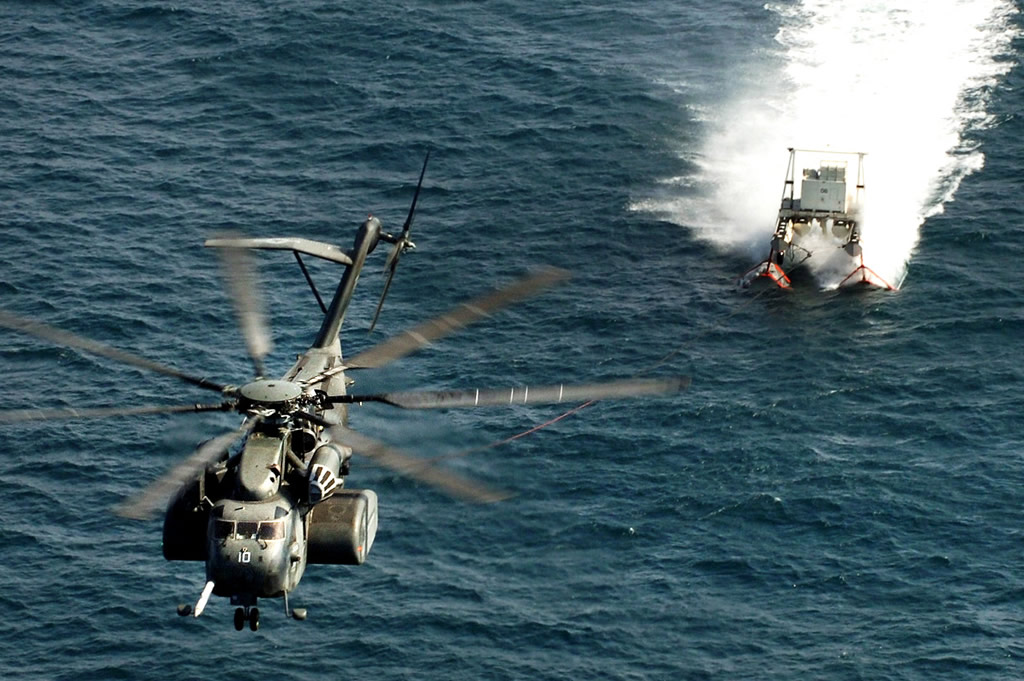
Tethered expendable communications buoy:
...
Special thanks to
SvenSvensonov for helping me put this together:
...
Antisubmarine warfare applications for autonomous underwater Vehicles:
1 Introduction
Traditionally the task of anti-submarine warfare (ASW) is a manpower and computationally intensive discipline. Various levels of sophisticated sensors gather large amounts of data, for example from towed arrays or sonobuoys, from which the relevant information, in terms of possible targets, threats, or false alarms, must be extracted. From this information a decision must be inferred by an operator or commander and a consequent action taken. Should the detection be ignored? Should it be passed on for further analysis? Should it be acted on directly, for instance by deploying a helicopter with a dipping sonar as a step towards the ultimate prosecution of the target?
We are investigating an alternative approach to traditional anti-submarine warfare. Rather than performing ASW with a single, large, high capability, capital ship or submarine working
individually (or with limited joint operations, e.g. a helicopter), we are investigating the concept of employing a system of many, small, limited capability, low-cost systems working in concert. In this case the sensors and underwater assets make collaborative decisions independent of an operator and carry out the necessary changes to their actions. The first goal in introducing this kind of autonomy is to optimize the detection, classification, and localization of a target. Of course, in order to make these decisions in real time, data processing must also be completed in real time. Processing on-board these small vehicles is typically limited by vehicle size, heat generation, and power constraints. A limited set of signal processing algorithms, compared to those which can be run on-board a large ship or submarine, must be chosen so that processing is possible without overly sacrificing performance. The sensors to be used for this kind of work may be bottomed non-acoustic sensors such as hydrophones or magnetometers or mobile systems such as gliders or powered AUVs pulling towed arrays. All technologies bring their own advantages and problems. We have focused on an AUV/towed array approach and the technology is described in Section 2.1.
The use of AUVs for ASW is a recent approach and not many research groups concern themselves with this field. Previous work has discussed vehicle control without processing (Benjamin et al., 2007), passive processing with an AUV using a nose-mounted array (Poulsen et al., 2006), or the use of kayaks, rather than AUVs, for 2D target tracking (Eickstedt and Benjamin, 2006). The feasibility of multistatic processing and tracking with AUVs has also been discussed (Lum et al., 2009), but the provided data was processed off-board. To the best of our knowledge, active sonar processing on board an AUV and subsequent use of the processed data has thus not been shown before.
Outside of ASW, most research has taken place into AUV navigation; among others concerning efficient path planning, both in the field of mine counter-measures and oceanography (Pˆetr`es et al., 2007; Kruger et al., 2007; Williams, 2010). Research has also
focused on making AUVs more adaptive to the environment, for example using simultaneous localization and mapping (SLAM) (Newman et al., 2003; Eustice, 2005; Barkby et al., 2009), and making them more adaptive to other vehicles through coordinated navigation and localization (Alvarez et al., 2009; Kalwa, 2009; Bahr et al., 2009).
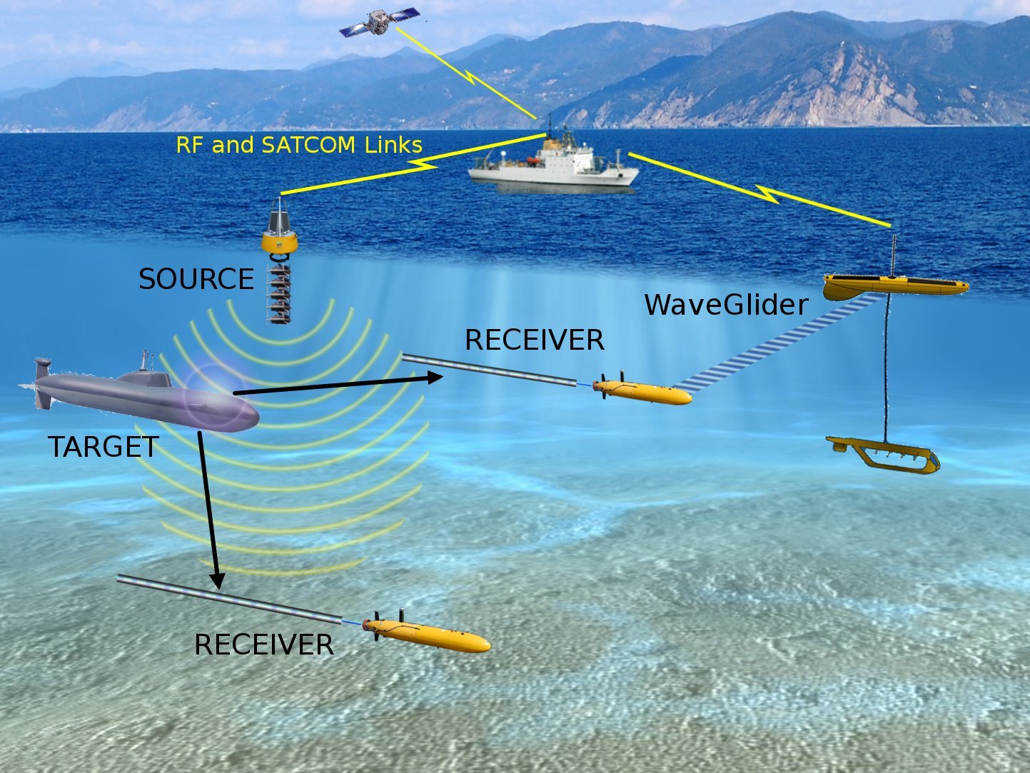
During the GLINT09 (Generic Littoral Interoperable Network Technology) sea trial, we overcame many of the previously mentioned hurdles and demonstrated an autonomous underwater vehicle (AUV) responding to towed array sensor data processed on-board the vehicle in real time. Our current system consists of a bi-static active sonar, relying on our previously developed expertise in, and equipment for, multistatic sonar and ASW (Ehlers, 2009). In a bi-static sonar, the source and receiver are spatially distributed. In our test we utilize a stationary, buoy mounted sound source. The receiver was a towed array pulled by our AUV. Our AUV was programmed using the MOOS-IvP (Mission Orientated Operating Suite-Interval Programming) software suite developed by our collaborators at the Massachusetts Institute of Technology (MIT), Naval Undersea Warfare Centre (NUWC), and Oxford University (Benjamin et al., 2009). MOOS-IvP provides the basic infrastructure and autonomy control for this system. To that, we have added our own suite of sensor signal processing and two adaptive behaviors.
This paper is laid out as follows: Section 2 gives an overview of the the GLINT09 sea trial, and the equipment and algorithms used are explained and parametrized in detail. In Section 2.3 specific details of the settings used in the sea trial are described. Section 3 shows results from the sea trial and comments are made on expected and obtained results. Conclusions are given in Section 4. Section 5 comments on some of the limitations in our current approach and how we intend to reconcile those over the next year.
1 Description of the GLINT09 sea trial
The GLINT09 sea trial was held between 29 June and 18 July 2009. The experiment took place in an area to the south-east of the island of Elba, close to the Formiche Islands off the coast of Italy. The area was ideally suited to an AUV based experiment because of its relatively flat bathymetry at a depth of approximately 110 meters.
Our primary platform of operations was the NATO research vessel NRV Alliance. The AUV was deployed and recovered from the Alliance daily. Additionally, our command center was set up in the lab area of the ship. Our sonar source, described below, was deployed from the Alliance and left in place for the duration of the trial. Also present was the coastal research vessel CRV Leonardo, which was used to tow an echo repeater target simulator for testing of the multistatic processor.
The goals of the experiment included a great deal of testing and data collection during the early stages. The ultimate objective, however, was to demonstrate an adaptive behavior on the AUV which uses the outputs of the real-time signal processing. At this early stage the demonstration was somewhat contrived. We utilized a high source level and had the AUV respond to the direct blast of the source, rather than responding to the target echo as is typical in sonar. Because the source was stationary and very high level, it enabled us to test the autonomy algorithm against an “easy”, high signal-to-noise ratio (SNR) target. We successfully performed true real-time bi-static sonar processing against the echo repeater test target towed by Leonardo, but did not couple that with the autonomy at this time.
The following sections describe the experimental equipment and processing algorithms used during the trial. Processing is described first in a general, parametrized sense. Then, the parameters and exact settings used during the trial are described.
1.1 Equipment
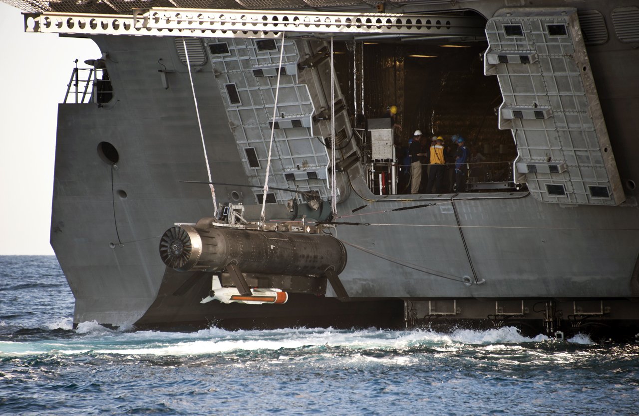
1.1.1 OEX AUV with SLITA towed array
The main tool of research for the GLINT09 trial was NURC’s Ocean Explorer (OEX) AUV used in combination with NURC’s
SLim
Towed
Array (SLITA). The OEX is an untethered AUV of 4.5 meters length and a diameter of 0.53 meters (21”). It can operate to a maximum depth of 300 meters. It has a maximum speed through the water when towing the array of 3 knots. Current battery constraints limit the lifetime of any mission to about 7 hours. The
OEX is equipped with two independent modems. One of these is a Wood Hole Oceanographic Institution (WHOI) modem (Freitag et al., 2005) which was used for communication of data with the command center. The second is an EdgeTech acoustic modem integrated with the vehicle main computer that sends vehicle location information only.
Figure: OEX AUV being lowered into the water. The towed source can be seen dangling behind the AUV, and further behind looping through the water is the start of the SLITA towed array.
The SLITA array used was actually an upgraded version of the one described in (Maguer et al., 2008). The array has a total of 83 hydrophones, with sets of 32 selected at any given time. There are four sets configured for optimal frequency spacings from 714Hz (105.0cm) to 3471Hz (21.0cm). This
range of frequencies allows us to operate in a passive lower-frequency mode as well as in an active, higher-frequency mode. The acoustic section starts 9 m behind the vehicle.
The array is also equipped with three compasses and two depth sensors that aid reconstruction of the array dynamics. Additionally, there is an active source which integrates with the array and can be towed by the AUV, allowing for future monostatic experimentation.
The OEX AUV itself is equiped with a main computer which directly commands the OEX’s control surfaces and maintains navigation. This main computer is capable of controlling the OEX for pre-planned autonomous missions, and for receiving basic commands via acoustic modem, which can order the OEX, for example, to abort a mission and surface. The LonTalk protocol is used by the vehicle computer for internal vehicle command and control messages.
The OEX also has a configurable mission payload section. It consists of two computer systems set up as pc-104
stacks: one for data acquisition from the SLITA array, the other for signal processing and MOOS-IvP autonomous decision making. The assignment of data acquisition to one computer and processing to the other is somewhat arbitrary, but is focused to provide ample processing power for data acquisition.
The pc-104 main boards in each stack have single core 1.4GHz Pentium-M processors with 1GB of RAM on board. These computers both run Linux operating systems, which aids in rapid development and ease of integration, even if not strictly a real time operating system. In our case, “real time” with respect to the data processing implies that processing is completed faster than new data comes in, and therefore can keep up with incoming data. The two payload computers are connected via Ethernet to each other, and via LonTalk to the vehicle main computer.
Data comes in from the SLITA array on 32 channels, one for each active hydrophone, through the A/D board, which is connected to the pc-104 acquisition stack via a PCI interface. Data is archived on the local acquisition computer’s hard drive, and also transferred via standard network file system (NFS) protocol to the hard drive connected to the MOOS/processing stack.
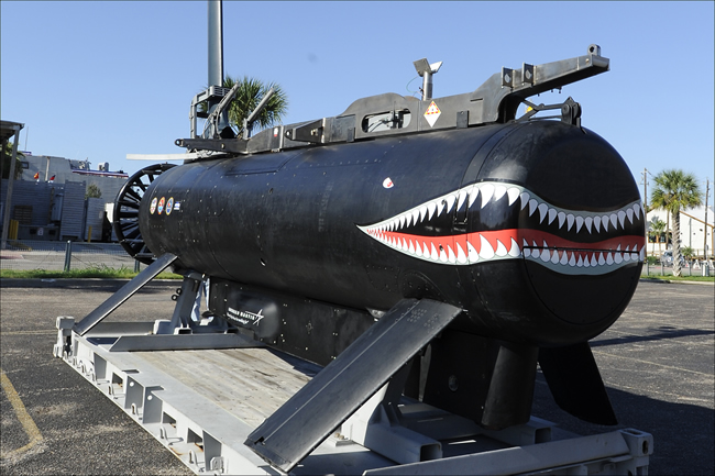
1.1.1 DEMUS acoustic source
The distributed multistatic underwater surveillance (DEMUS) source, is a programmable bottom-tethered acoustic source based on free-flooded ring technology. It has a maximum source level of 217 dB, and a programmable acoustic frequency range from between 2 and 4.2kHz. A radio buoy floats on the surface attached to the source so that the acoustic signals to be transmitted can be altered by means of a radio connection. The radio buoy also has a GPS which provides very accurate transmission timing and source position localization. Accurate timing and localization of the source are critical inputs for accurate bi-static sonar processing.
The acoustic source is also equipped with a WHOI acoustic modem which allows it to be turned on and off remotely by means of acoustic communications. This allows our AUVs to trigger the source to start pinging, for example after making a passive detection. This particular capability was not used in this trial, although we have effectively tested it.
Figure: The DEMUS acoustic source being deployed (left). The eight free-flooded transducer rings are visible on top, with the electronics canister underneath. The DEMUS surface buoy (right) is shown during a battery replacement. GPS and radio command antennae are visible on top.
1.1 Algorithms and software implementation
1.1.1 MOOS-IvP
The signal processing and decision-making engine utilized MOOS-IvP as its underlying software infrastructure. MOOS-IvP has two primary functionalities (Benjamin et al., 2009). First, it provides a basic suite of AUV autonomy processes for navigation, control, acoustic communications, etc. The IvP-helm process in this suite specifically enables the use of multiple “behaviors”. Different behaviors (e.g. obstacle avoidance or course following) are active at the same time and their weighting determines their importance towards the output. IvPhelm combines the objective functions of each behavior to determine AUV heading, speed and depth (Benjamin, 2004).
The second function provided by MOOS is interprocess communications (IPC). Information can be shared between processes through a publish-subscribe structure to the MOOS database (Benjamin et al., 2009). By providing this middleware layer of communication, new processes may be added quickly and easily, and may interact with legacy processes or replace them. The MOOS database also provides for convenient logging of data. All messages published to the database can be archived, along with timestamps and process of origin name.
The MOOS-IvP helm control integrates with the OEX vehicle using a “front-seat driver/back-seat driver” paradigm. The OEX vehicle main computer acts as the “front-seat driver”, directly manipulating the vehicle control surfaces, maintaining trim, etc. The payload computer, specifically the MOOS/processing stack described in 2.1.1, acts as the “back-seat driver”. MOOS-IvP decides the direction, speed and depth for the vehicle. This can be the result of mission parameters, the IvP behavior solutions, and the real-time data acquisition and processing. The desired heading, depth and speed are sent to the front-seat driver computer, which then actually performs the necessary maneuvering. This model
provides for a convenient fail-safe should the back-seat driver computer fail or begin to drive the vehicle out of area. The vehicle main computer can also be cued via acoustic modem to ignore back-seat driver commands, or it may take over and make the AUV return to base or surface should it cease to receive information from the back-seat driver.
At NURC we are building on the infrastructure provided by MOOS-IvP. We have introduced a real-time signal processing capability which analyses every ping, forming contacts and ultimately forming tracks. The implementation of a fully functioning active ASW signal processing chain on a PC104 stack has been a challenge and the steps taken to make it possible are detailed in the next section, 2.2.2.
With the sonar signal processing in place the algorithm designer can start to consider how the AUV should react to its world view. In Section 2.2.3 we discuss, in detail, a simple adaptive behaviour which illustrates what can be done and we discuss how it was demonstrated at sea.
1.1.1 Sonar signal processing
The signal processing suite was developed using a combination of algorithms and previous software by MIT for similar active sonar processing (Lum et al., 2009) and from NURC’s previous multistatic processors (Laterveer, 2003; Baldacci and Haralabus, 2006). The implemented signal processor is a frequency-domain, configurable band, conventional beamformer and matched filter library for a line array. A MOOS-IvP front end interface,
pProcessSlita, was created for this library to allow the publication of acoustic detections to the MOOS database. This section gives a general description and parametrization of the algorithm employed. Details on the settings used for the experiments are given in Section 2.3.
Data for each channel (or hydrophone) of the receiving array is recorded into a file at the
sampling rate. The data file is then moved from the acquisition stack to the processing stack as described in Section 2.1.1. The signal processor detects the creation of the new file and reads it into memory. Array/hydrophone data was not transferred through the MOOS database, as MOOS is designed to handle text-based messages or short data transfers. The large data bandwidth required for the hydrophone data made direct reading from the file more efficient.
Once the file is read, the processor moves through the following signal processing stages. Fourier transform to frequency domain, frequency domain beamforming, matched filtering using overlap-save method, inverse Fourier transform, along-beam (1-D) normalization, and contact formation.
Fourier transform
The data is first transformed into the frequency domain. Since the data timeseries is real valued, the discreet Fourier Transform is Hermitian symmetric. This means that only the positive frequencies need to be computed and processed, the negative frequencies being redundant. The transform was performed using the Fast-Fourier Transform (FFT) in the Newmat library (Davies, 2006) during the GLINT09 sea trial, but has subsequently been upgraded to the FFTW library (Frigo and Johnson, 2005).
FFT’s are performed in overlapped segments or “snapshots”. The overlap length is dictated by the overlap-save method to be the length of the matched filter (Proakis and Manolakis, 1996). In this case, the 1-second length of the active sonar pulse is used. The length of the FFT itself is configurable. Given trade-offs in FFT processing vs. overlap length, (Borgerding, 2007) suggests a power-of-two FFT length about four times the length of the matched filter, but this should be tested on target hardware to find the fastest FFT length. The first segment is zero padded at the beginning by the overlap length. This end effect is accounted for by overlap with the subsequent segment.
Beamforming
Beamforming is performed in the frequency domain over a selected band. Conventional frequency-domain beamforming is used as described by (Johnson and Dudgeon, 1993). In each of the equations below, the frequency
ω processed included only the selected band w = [wc −
BW/2 : wc +
BW/2], where wc is the center frequency and
BW is the bandwidth of the active pulse. Beam pointing directions can be cosine spaced or linear. Cosine spacing is often used since main lobe width is constant in cosine space for a conventional beamformer using an equally spaced line array.
For efficiency during the running of the processor, these frequency domain complex steering coefficients are precomputed at initialization for each beam pointing direction.
Matched filter & inverse Fourier tranform
The matched filter is implemented with the overlap-save method. After matched filtering, data is transformed back into the time domain using the inverse Fourier transform. Overlapped portions are discarded as per the overlap-save method. This process repeats until not enough new data remains in the file for another complete segment to be processed. The rest of the data is discarded, resulting in a small data loss at the end of each file. The exact amount depends on the the selected FFT sizes, overlaps, and length of time series in the file. This loss could be mitigated by saving the data over time from sequential files, and continuing the overlap-save process. Indeed, this type of continuous processing capability was initially envisioned, but at this time was not required or implemented.
Normalization
The data is now in the form of matched filter output beam timeseries. Normalization is performed in the time domain down each beam with a split-window method normalizer as described in (Baldacci and Haralabus, 2006). For each point in the time series, leading and lagging sample windows are used to compute the mean noise level. A guard band separates the sample to be normalized from the noise estimation window to avoid signal contamination in the noise estimate. The data point is normalized by the computed mean noise in the noise estimation windows. At the beginning and end of the time series, these windows are smaller due to the end effects. For example, the first sample has only the noise estimate from the leading window. As the windows are applied to data at increased distances from the beginning of the file, the noise estimate from the lagging window is gradually added. Similar effects occur at the end of the timeseries.
Contact formation
Once we have the normalized timeseries, we utilize a very simple detector/classifier: The three highest SNR range-bearing points are returned by the processor. The strongest rangebearing point is selected and output as the first contact. Since a detection usually consists of several range-bearing points in a cluster, data along that range and beam (bearing) are then masked out. The process is then repeated with the second and third strongest range-bearing points. This process of masking is a simplistic version of solving the clustering problem, preventing multiple detections from forming on the main response lobe of a single actual target. However, as a result, only one detection can be found on any given bearing or at any specific range. This crude contact formation/classification method was adequate during GLINT09 for proof-of-concept. The vehicle was tasked to track the source, which was always the strongest contact, or the echo repeater, also set with high levels and therefore always the second strongest contact. In the future we intend to implement a constant false alarm rate (CFAR) style algorithm for this process, similar to the one in (Baldacci and Haralabus, 2006).
1.1.1 Behaviors
The behaviors are developed within the MOOS-IvP software framework described in Section 2.2.1. The behavior parameters are specified in a behavior file, which itself is referenced in the pHelmIvP process configuration block of the overall mission configuration file. These mission configuration files are loaded onto the OEX payload computer before deployment.
Two behaviors were developed for the GLINT09 sea trial: an adaptive loiter and an adaptive broadside behavior. The term “broadside” refers to the target bearing relative to the acoustic array. In the case of a vehicle towing an array straight behind it, broadside is 90 degrees relative to
the heading of the vehicle. When a target is at broadside to the array, the full aperture of the array is applied to resolve the bearing. Conversely, a target at or near “endfire”.
Adaptive loiter
The
adaptive loiter behavior is an adaptation of the standard loiter behavior that is part of MOOS-IvP (BHV Loiter in (Benjamin et al., 2009)). The standard loiter behavior sets waypoints for the vehicle using a closed path polygon. The vehicle drives around this polygon repeatedly. The
adaptive loiter differs from a standard loiter by examining the highest SNR contact in the MOOS database as it drives in this polygon pattern. If the SNR value of that contact is being actively updated and exceeds the
SNR threshold parameter, the AUV will switch to the mission specified by the
alternative mission parameter. This means that the AUV can start out in the
adaptive loiter, and automatically switch to the
adaptive broadside upon incoming high-SNR contacts. The important parameters for automatic mission switching in the adaptive loiter are therefore the
SNR threshold and
alternative mission.
A message is sent via acoustic modem to switch into the adaptive loiter. As explained in the previous paragraph, the AUV then loiters until it observes a contact in the MOOS database with an SNR higher than the
SNR threshold. The AUV then switches to its
alternative mission, which is the adaptive broadside behavior.
Adaptive broadside
For the adaptive broadside behavior, there are nine parameters. Five of these parameters exist solely for the purpose of switching to other behaviors. These are the
SNR threshold,
SNR timeout,
alternative mission,
run timeout and
timeout mission. If the SNR of the
retrieved contact is smaller than the
SNR threshold for the number of sequential contacts (pings) specified by the
SNR timeout, it will switch to an
alternative mission. In this case the adaptive loiter behavior was used, as shown in Figure 8. The
run timeout is a global timeout of the adaptive broadside behavior (specified in seconds or “no-time-limit”), after which it will switch to an alternative mission, parameterized as the
timeout mission so as not to confuse it with the alternative mission, used when no high SNR contacts are found.
The remaining four behavior parameters are:
•
side: the side the target is expected on (needs to be predefined because there is no port-starboard discrimination).
• adaptive angle: the desired angle between the AUV’s (and towed array’s) heading and the target position (0◦ − 180◦),
•
maximum turn angle: constraint on heading change per incoming contact, set between 0 and 10
degrees. Introduced to prevent the vehicle from turning sharply and bending the array to the point where the beamforming fails.
•
heading before start: desired heading at start of the broadside behavior (0−360deg).
Two of these parameters were introduced to mitigate limitations of the physical dynamics of the SLITA array. The
heading before start makes sure the array is straight and the target is on the expected side before the adaptive broadside takes over. The
maximum turn angle ensures the towed array is sufficiently straight for line array beamforming.
When the broadside behavior becomes active, the AUV starts with straightening its array to the
heading before start value. Once this is done, the bearing to the target, passed from pProcessSlita via the MOOS database (RELATIVE BEARING) to the behavior , is used to calculate a new heading for the AUV.
As has been mentioned, the
side parameter is needed to define on which side of the array the target is expected due to the lack of port-starboard discrimination. In a more realistic scenario, the port-starboard discrimination could be performed via vehicle maneuvers, or by means of a more complex array configuration. We are currently pursuing both aveneus in parallel for future work.
1.1 Mission setup for GLINT09
This section describes specific settings used by the algorithms during the GLINT09 field trials. Parameter values used for the processing as well as the behaviors are provided. Finally, there is a description of the test geometry and expected vehicle path.
Active sonar pings from the acoustic source occurred every 12 seconds and were one second long. Pings were linear frequency modulated (LFM) up-sweeps with center frequency of 2950Hz and 200Hz bandwidth. The source level was set to 212dB re 1
µPa. The highest frequency spacing on the SLITA array was used, which provides for half wavelength spacing at 3471Hz. The acquisition system on-board the OEX recorded data at 6275Hz sampling rate, a compromise between various acquisition board buffer sizes and desired output file size.
Due to the 12 second ping repetition interval, timeseries data for each of the 32 active hydrophones in the array was recorded into 12 second long files. This 12 second data length implies a maximum range limit of approximately 9000m (assuming 1500m/s sound speed). Every second ping/file was utilized by the signal processing, while alternate pings were ignored. Just before the GLINT09 sea trial, benchmarking indicated that processing 12 seconds of data required approximately 12 seconds on the vehicle’s processing computer. However, given the experimental nature of the trial, the load on the processing stack changed as various processes were added or removed. Being conservative, utilizing every second data file allowed 24 seconds for the processing to complete. In fact, the trial logs showed that processing during the trial required about 13.5 seconds when the processing stack was fully loaded.
An FFT length of 16384 samples and an overlap of 6375 samples (or 1 second, due to the matched filter of the 1 second long active pulse) was used. This yielded seven overlapped segments per file. A Hanning window was used for temporal windowing to reduce sidelobe ringing. For beamforming, 41 cosine spaced beams were formed. The elements of the array were Hanning shaded for beamforming as well to reduce spatial sidelobes. For both matched filtering and beamforming, frequency bins from 2850-3050Hz were processed. This was equivalent to a frequency domain bandpass filter around the active pulse band. This was not explicitly windowed or shaded. However, the active pulse itself was windowed in time with a Tukey window 5% on each end, which amounted to frequency windowing for an LFM pulse. This provided adequate de-facto windowing.
For the adaptive loiter the same
SNR threshold was used and the
alternative mission was the broadside behavior. Although for true broadside one would expect an
adaptive angle of 90
degrees, simulation results showed that delays between data acquisition and the actual turn command, as well as the imposed
maximum turn angle, meant that a shallower angle was required in order to maintain a circle around the static contact.
The AUV was set up to start in a standard loiter behavior (black square). A signal was then sent from the command ship via acoustic modem to switch to the adaptive loiter behavior (pink dashed square). The AUV then began to monitor acoustic data for incoming contacts.
Parameters for broadside behaviour during GLINT09 detected that exceeded the SNR threshold, the AUV automatically switched to the adaptive broadside behavior and began to drive in a circle (pink, dashed) around the contact (the static acoustic source). The
run timeout parameter was set to 800 seconds, which gave the AUV time to travel a quarter of a circle around the acoustic source before switching back to the standard loiter. The center of the standard loiter was set at the starting location, therefore the AUV returned to that location.
This somewhat artificial scenario was used to test the localization and basic detection capabilities of the signal processing algorithm, as well as the broadside behavior responding to that signal processing. In a more realistic ASW scenario, there are many issues with low SNR target strength and false alarms. These will be dealt with in future developments and improvements in CFAR detection, tracking (which integrates data over time decreasing some false alarms) and tracker tuning, and classification algorithms to distinguish between clutter and targets. These algorithms will exploit the AUV’s maneuverability through coupling with vehicle behaviours.
Conclusions
Anti-submarine warfare (ASW) has traditionally been carried out by means of submarines or frigates with towed arrays searching for submarines. AUVs are seen as a possible addition to the field of anti-submarine warfare, with the potential of being part of a multistatic active sonar network. Their benefits also include covertness, reduced risk, reduced man power, potential persistence and the ability to optimize sensor position in 3D space based on incoming sensor data. Until now, progress on these systems has been slow because of the challenges concerned with developing sophisticated real-time systems, and having the individual sensors or the system as a whole to act autonomously.
This paper has described the on-board signal processing suite developed for the OEX AUV at NURC. During the GLINT09 sea trial the adaptive loiter and broadside behaviors were tested on the OEX AUV with a real-time processing payload in combination with the SLITA array and DEMUS acoustic source. The OEX achieved keeping a target at broadside well enough to complete a quarter of a circle around the target. Automatic switching between behaviors, from adaptive loiter to adaptive broadside, and from adaptive broadside to a standard loiter, was also demonstrated.
In summary, this paper has provided a detailed description of the on-board real-time sonar signal processing developed, and shown successful initial adaptive behaviors that operate on the output. To the best of our knowledge, the behaviors demonstrated are the first adaptive behaviors for AUVs in ASW applications that have been reported for a field trial, using realtime on-board processing. These results set the stage for making AUVs more autonomous for ASW applications.
Future research
For the real-time signal processing, several improvements to the processor need to be put into place to create a more realistic ASW environment. A proper CFAR (constant false alarm rate) implementation with thresholding and detection will be implemented, as well as a tracker. While the active detection and tracking of submarines is a non-trivial matter, NURC will leverage its experience in this field to implement state-of-the-art algorithms to the extent possible in a real time system with limited processing. NURC has these algorithms in house - quick implementation is the only requirement at this point. Indeed, certain speed-ups have already been put into place for the existing signal processing software since GLINT09, resulting in a measured speed-up of almost 30%. Current benchmarks show the we can process a 12 second data file in less than 4 seconds on-board the vehicle.
During the next sea trial, GLINT10, planned for July/August 2010, we intend to test these signal processing algorithms with improved adaptive behaviors. This will include a more thorough analysis of future simulation performance and characterization of the used and optimum values for the developed behaviors. Specifically, we intend to track a moving echo repeater, as opposed to circling a static, loud source. The echo repeater’s level can be adjusted to make the processing and tracking more or less difficult. Primarily, we hope to test behaviors which reach a compromise between keeping the target at broadside (for best localization) and staying close enough to the target to form a contact and hold track.
Future behaviors will utilize new hardware that is being developed at NURC, such as directional arrays. The construction of a second AUV at NURC (from OEX parts), will allow us to begin developing cooperative behaviors. Using the AUVs as homogeneous entities, or perhaps as heterogeneous vehicles with different capabilities.
References
Alvarez, A., Caffaz, A., Caiti, A., Casalino, G., Gualdesi, L., Turetta, A., and Viviani, R. (2009). F`olaga: A low-cost autonomous underwater vehicle combining glider and AUV capabilities.
Ocean Engineering, 36(1):24–38.
Bahr, A., Walter, M. R., and Leonard, J. J. (2009). Consistent cooperative localization. In
Proceedings of the IEEE International Conference on Robotics and Automation (ICRA), Kobe, Japan.
Baldacci, A. and Haralabus, G. (2006). Signal processing for an active sonar system suitable for advanced sensor technology applications and environmental adaption schemes. In
EUSIPCO 2006, Florence, Italy. European Signal Processing Conference.
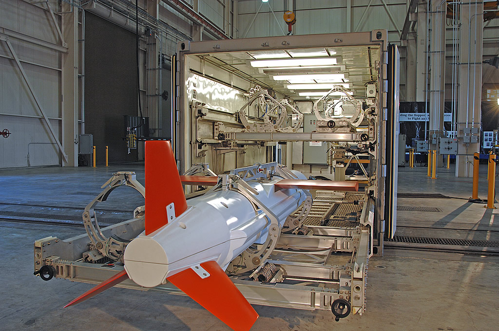
Eagle Ray
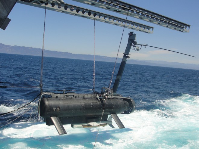
Girona 500
@Armstrong @Gufi @Nihonjin1051 and anyone else interested in the applicability of AUVs for AWS.


 ATR 72 ASW is produced by Alenia Aermacchi.
 ATR 72-600 served as the base platform for ATR 72 ASW.


 .
.