What's new

Fundamentals of Stealth Design & Concepts of RCS Reduction

India is trying to use some technologies from PAK-FA to implement some degree of stealth( like painting with Radar absorbant materials). i have read some reports that it was successful in reducing the overall radar signature of existing design and in future india will definitely experiment with hypersonic Brahmos on su 30MKI :cheers:
Painting it with radar absorbing material will not be much effective on Su30, you know why ... because probably 90% of the RCS generated by Su30 is because of its massive engines being visible from front (from within FOD filter) and because of its two HUGE tails. This is the same problems US had with F14 & F15.

Why waste expensive paint on Su30 when its not going to give much of a difference.
There are some benefits, else Boeing would not have produced the F-15 Silent Eagle. That said...The Su-series, and that include the J-11, may not be as amenable to the application of RAM and the even more drastic measure of airframe and planform modifications. Not technically impossible, just may be not as worthwhile in terms of cost/benefits analysis.

Here is why...

simu_aircr_scatterers.jpg


An aircraft is first and foremost, for any attempt at RCS reduction, a complex body. Failure to accept this fact will result in wasted resources and under a dictatorial regime, loss of one's head in payment for those wasted resources. For radar detection, a complex body is a 'Swerling' type target...

Peak Detection of Swerling type Targets. Part 1. Detection Probabilities in White Noise
Peak detection is an alternative to the commonly used threshold detection scheme in radar systems. The present report is the first part in an investigation of peak detection performance, for Swerling type targets, in an arbitrary noise/clutter background. In this report, peak detection is compared with classic fixed threshold detection in uncorrelated white noise. A methodology is also developed, capable of handling arbitrary stochastic signal and noise/clutter models.
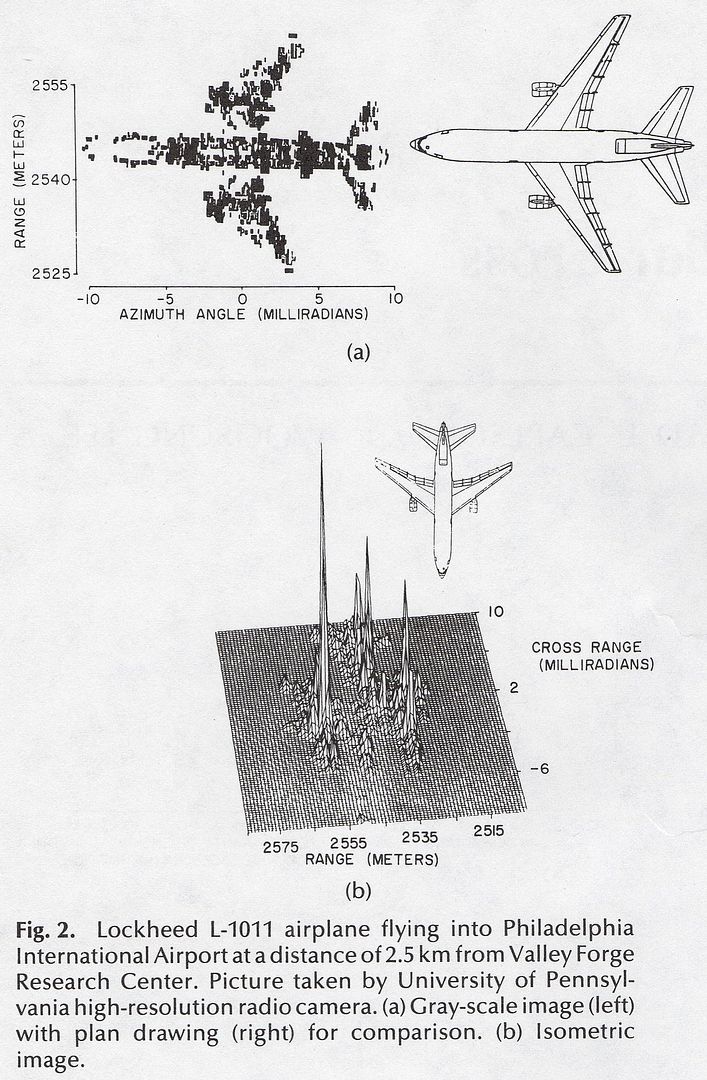
Basically...A complex body ALWAYS produces diverse echo points from its many different surfaces. Against background radiation, or 'clutter', these diverse echoes not only stands out but also clustered. Some of the smaller echoes will fall within the clutter region and will be filtered out by the radar computer. Some of the smaller echoes may come from a sharp edge, like the leading edge of a wing, and when the aircraft execute a maneuver, this particular surface can come to be the dominant echo in the total RCS summation.

Threshold detection algorithms just simply remember any and all echo points that rose above the clutter region and keep that cluster in memory -- a 'target' is qualified and displayed on the scope. Peak detection scheme is more complex in that not only does the radar computer begin recording an echo point that is above clutter but continue recording until that echo die. The result is the above image that contain a 3-axes graphical locations of those echo points and a 'stickman' like aircraft composited from those echo points. Threshold detection scheme is unofficially 'good enough' for F-15 equivalent bodies and that include the Su-series. Peak detection scheme is best against F-16 equivalent bodies and that include the single engine J-10.

These echo points varies not only from scan to scan -- main beam movement -- but from pulse to pulse -- inside the transmission itself. So it is clear that against US 'stealth' aircrafts, peak detection scheme is required but remain doubtful that a target is qualified since their bodies, including the estimated highest echo points, are designed to be reflective within the clutter region. The word 'doubtful' here is intended to be taken in a statistical context, not that those echo points are nonexistent. They are very real. The word 'complex' refers to EVERYTHING on the body and for military aircrafts, that includes miscellaneous items like pylons and the protruding bolts that attach them to the wings, ordnance, the many antennas types, etc...etc...If a radar system is primitive enough to have only a threshold detection scheme, it is likely that it will display an F-22 or F-35 only within visual range, but then it will be too late.

b-2_profiles.jpg


yaw_rcs_b2-sim.jpg


roll_rcs_b2-sim.jpg


pitch_rcs_b2-sim.jpg


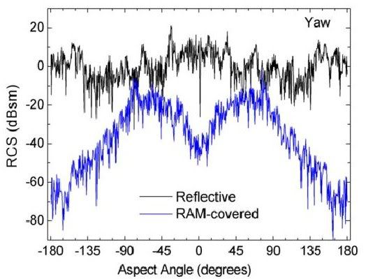
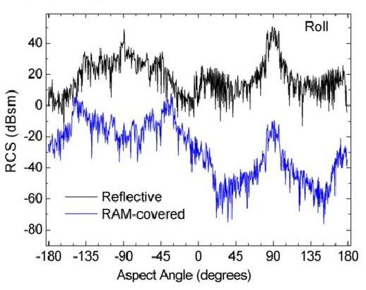
CAUTION...DO NOT for a moment believe that those are the true RCS figures of the B-2. The aircraft's general physical profiles are public enough since we flew the aircraft to many places in the world. What we see are estimated figures ran through a predictive RCS program that happened to include commercially available RAM, such as those applied to airport radomes, and their electrical properties are also public knowledge. What RAM that is actually applied to the B-2 is secret, of course.

For each axis, the aircraft is rotated and its RCS is recorded throughout the movement. For pitch, imagine the aircraft is rotating nose-up or nose-down while the viewer is looking at the aircraft's straight on. The highest peaks are when the viewer is looking at the top and bottom of the aircraft. For roll, the viewer is looking at a wing tip and the aircraft is rotated wing tip up or wing tip down. Keep in mind the cockpit and engine intake bulges on the aircraft's topside while the bottom is relatively more even. For yaw, the viewer is looking at the aircraft's either from a nose on or exhaust perspective and the aircraft is rotated sideways.

The question is whether or not applying RAM to the Su-series, and that include the J-11, will yield a net RCS reduction figures as how the B-2 was so reduced. The answer require that we put the basic Su body through intensive physical measurements and at the very least a predictive RCS reduction computer program. How good is that software? That is a chance someone with sufficient authority has to take. The better alternative is to actually apply one of these commercially available RAM to a clean body, take it out on a radar range, assuming one has such facilities, and perform comparative radar measurements.

It would not be honest to use the 'cost is no object' argument since any application of RAM will yield a net RCS reduction and if cost is not an obstacle then even a %.0001 net reduction is worth the effort, therefore this debate is pointless. The question is made even more complicated by the fact that an RCS figure decreases as distance increases. So if there is a net RCS reduction figure, at what distance in a closing situation, will this reduction is worth the investment? A reduction that decreases effective detection range from 200km down to 190km is not really worth the investment. But if the reduction decreased effective detection range from 200km to 150km or lower, in other words, the attacker is 50km closer to his targets before the defenders are alerted to his presence, then it might be worth considering. What if one side gained 50km but the other side, due to technology issues, gained only 10km, on the same or similar body type?

Because an aircraft is a complex body and given the fact that other than the US, the world is still struggling with passive RCS techniques such as RAM, it might be better to discard RAM as a consideration and concentrate on weapons related issues. The Su basic body may not be so financially worthwhile UNTIL an extensive technical investigation is performed. If during this investigative period, it is found that the basic Su body, even with RAM applied and there is a net RCS reduction, can still be detected with the less sophisticated threshold detection scheme, then it would not be worth the modification. Since the detection scheme, standard threshold or the more sophisticated peak method, is on 'the other side', the issue is not confined to merely how much in percentage is the reduction but also include how good is the enemy's radar capabilities. If 'the other side' found out that his enemy's radar capabilities is not comparable to his own, and if he can afford the investment, then what was previously thought as not worthwhile may be very worthwhile after all.

Who does NOT need the more sophisticated peak detection method? How about civilian air traffic controllers? What need are there for them to pick up large airliners that also carries transponders? The RAM subject in this debate, because it involve an honest assessment of one's potential enemies and their detection capabilities, is not a straight forward 'Yea' or 'Nay' answer.
some more info by gambit
 
Goal of Stealth Technology

The goal of stealth technology is to make an airplane as invisible (currently 5th Gen Aircrafts are called Stealth Fighters) to radar as possible. In simple terms, current stealth technology allows an aircraft to be partially invisible to Radar or any other means of detection. This doesn't allow the aircraft to be fully invisible on radar (which is a common mis perception). Stealth technology cannot make the aircraft invisible to enemy or friendly radar (current technology). All it can do is to reduce the detection range or an aircraft depending on the design of stealth.

There are two different ways to create invisibility:

  1. The airplane can be shaped so that any radar signals it reflects are reflected away from the radar equipment.
  2. The airplane can be covered in materials that absorb radar signals.

Let's watch this video by Lockheed Martin:


Most conventional aircraft have a rounded shape. This shape makes them aerodynamic, but it also creates a very efficient radar reflector. The round shape means that no matter where the radar signal hits the plane, some of the signal gets reflected back:

stealth-1a.jpg

A stealth aircraft, on the other hand, is made up of completely flat surfaces and very sharp edges. When a radar signal hits a stealth plane, the signal reflects away at an angle, like this:

stealth-2a.jpg

In addition, surfaces on a stealth aircraft can be treated so they absorb radar energy as well. The overall result is that a stealth aircraft can have the radar signature of a small bird rather than an airplane. The only exception is when the plane banks -- there will often be a moment when one of the panels of the plane will perfectly reflect a burst of radar energy back to the antenna. So angels matter a lot too.

So how does this work?

The level of stealth an aircraft can achieve depends totally on the design and the substance with which it is made of.

RAS

RAS or Radar absorbent surfaces are the surfaces on the aircraft, which can deflect the incoming radar waves and reduce the detection range. RAS works due to the angles at which the structures on the aircraft's fuselage or the fuselage itself are placed. These structures can be anything from wings to a refueling boom on the aircraft.

The concept behind the RAS is that of reflecting a light beam from a torch with a mirror. The angle at which the reflection takes place is also more important. When we consider a mirror being rotated from 0 degree angle to 90 degree angle, the amount of light that is reflected in the direction of the light beam is more. At 90 degree angle, maximum amount of light that is reflected back to same direction as the light beam's source. On the other hand when the mirror is tilted above 90degree angle and as it proceeds to 180 degree angle, the amount of light reflected in the same direction decreases drastically.

RAM

Radar absorbent surfaces absorb the incoming radar waves rather than deflecting it in another direction. RAS totally depends on the material with which the surface of the aircraft is made.

IR

Another important factor that influences the stealth capability of an aircraft is the IR (infrared) signature given out by the plane. Usually planes are visible in thermal imaging systems because of the high temperature exhaust they give out. This is a great disadvantage to stealth aircraft as missiles also have IR guidance system. The IR signatures of stealth aircraft are minute when compared to the signature of a conventional fighter or any other military aircraft.

If reducing the radar signature of an aircraft is tough, then reducing the IR signature of the aircraft is tougher. It will be like flying a plane with no engines. The reduced IR signature totally depends on the engine and where the engine is placed in an aircraft.

Engines for stealth aircraft are specifically built to have a very low IR signature. The technology behind this is top secret like others in stealth aircraft. Another main aspect that reduces the IR signature of a stealth aircraft is to place the engines deep into the fuselage.

OK, cool but is this it?

No, current stealth technology uses other methods by which they decrease there chance of being detected.

  • One of the main efforts taken by designers of the stealth aircraft of today is to carry the weapons payload of the aircraft internally. This has shown that carrying weapons internally can considerably decrease the radar cross-section of the aircraft. Bombs and Missiles have a tendency to reflect the incoming radar waves to a higher extent. Providing missiles with RAM and RAS is an impossible by the cost of these things. Thus the missiles are carried in internal bombays which are opened only when the weapons are released.
  • Radars can use the radar waves or electro-magnetic energy of planes radar and locate it. An aircraft can remain undetected (depending on range) just by turning the radar off.
  • Plasma stealth technology is what can be called as "Active stealth technology" in scientific terms. This technology was first developed by the Russians. It is a milestone in the field of stealth technology. In plasma stealth, the aircraft injects a stream of plasma in front of the aircraft. The plasma will cover the entire body of the fighter and will absorb most of the electromagnetic energy of the radar waves, thus making the aircraft difficult to detect.

WOW... This is super great... it is too good...

Hold on skippy it has some disadvantages too...

  • Stealth aircraft cannot fly as fast or is not maneuverable like conventional aircraft. But the work is in progress and soon this will be corrected as technology improves. F22 is a great example which can go upto Mach 2 speed.
  • Reduced amount of pay load since since it needs to be carried internally (to remain stealth).

Damn... what if my country demands it to carry more pay load?

Well if there are enough slots it can carry them, however then it won't be stealth and above mentioned disadvantages will put them in more danger against faster and more maneuverable 4.5 gen aircraft. Remember... all Stealth's are fighters (they can be stealth or no stealth depending on the mission) however all fighters are NOT stealth.


Ref:
STEALTH TECHNOLOGY
.::What is Stealth Technology?::.
HowStuffWorks "How does stealth technology work?"
 
Last edited by a moderator:
Very good technology but this aircraft is very old. The concept is to make a flat bed aircraft with sharp edges. More the below surface is flat, there are less chances of detection. Other than this, they are using bird aircrafts which are remote controlled with cameras. They are not detectable able in radars. Although small but excellent technology.
Currently US has a very latest version of stealth bomber that vanishes totally from the radar. Also India Pakistan has the radars made by Russia or USA. So they keep those factors in mind when making such planes. they know the weaknesses very well than us .
 
Most conventional aircraft have a rounded shape. This shape makes them aerodynamic, but it also creates a very efficient radar reflector. The round shape means that no matter where the radar signal hits the plane, some of the signal gets reflected back:

stealth-1a.jpg

A stealth aircraft, on the other hand, is made up of completely flat surfaces and very sharp edges. When a radar signal hits a stealth plane, the signal reflects away at an angle, like this:

stealth-2a.jpg
This section is not technically incorrect, but it is technically incomplete.
 
Gambit sir, it was meant to be a beginners guide who wonders what is stealth. I made a seperate thread on the same, but seem mods merged it :D

This section is not technically incorrect, but it is technically incomplete.
 
Most do not have even a rough idea of what kind of computational power that is needed to calculate the contributorship of a mess like this...

jdam_gbu30.jpg


...Towards and final and total radar cross section of the aircraft. The word 'contributorship' is important because it precisely describe EVERYTHING on a complex body that create the impression of a radar cross section (RCS). External stores may be discarded but until they are discarded, they remains important and attached to that RCS value. On the other hand, the pilot, the wings, the engines, and many more simply cannot be discarded. Their contributorship can be manipulated in some ways to reduce the levels of their contribution and it is in that manipulation that is proverbially 'classified' and mysterious to the laymen.

Here is an indicator of how complex is the task and how much computational power is required...

Computers sweat for 4,554 hours to simulate cloth movement | Crave - CNET
It took 4,554 CPU hours to generate 33 gigabytes of data aimed at figuring out the many ways a piece of cloth can move.
Over 4500 CPU hours just to generate 33 GB of data of cloth waving around on a human body and there are flash drives that are larger than 33 GB.

An aircraft is a dynamic target, meaning whatever impression it presents, visual spectrum or EM or IR, changes in relation to whatever facet it presents to the viewer. That is why those impressions, visual spectrum or EM or IR, are often called 'fictitious' by engineers. The word 'fictitious' does not mean these engineers made these values up. It just simply means they are not constant and for radar engineers trying to 'counter-stealth', it is their UNRELIABILITY that is problematic for what they are tasked to do: detect low radar observable bodies.

Moving cloth because of wind or body changes is no different than an aircraft altering its facets to the seeking radar. The dynamics of moving cloth is ideal illustration because it directly affect the viewer, in this case, it is the game player. The game designer requires over 4500 CPU hours just to generate 33 GB of cloth movement data and even that is not enough to convince the game player that he cannot distinguish computer generated cloth from a piece of real material. The goal is not to mislead the player that he is seeing a filmed motion picture but to tell him that these 33 GB data of cloth is indistinguishable from the real cloth, even though he know he is watching a simulation of the real thing.

The 'stealth' aircraft designer must do the same as the game designer in principle: He must shape this design in a way that will convince the seeking radar that it cannot distinguish the aircraft from background noise EVEN THOUGH THE SEEKING RADAR KNOWS THAT THERE ARE BACKGROUND NOISE AND THERE IS A 'STEALTH' AIRCRAFT IN THAT NOISE.

For the game designer, if his character is being obscured by smoke, he must compensate so that the moving cloth is no longer visible to the game player. No difference for the 'stealth' and 'counter-stealth' dynamics. The transmitting signals are affected by distance and atmospheric losses. So do the the reflected signals. The 'stealth' aircraft designer know this and tries to exploit this factor into his shaping. The 'counter-stealth' radar designer know this and tries to optimize his data extraction algorithm as well as getting the best hardware he can.

Currently, the advantage is on the 'stealth' aircraft designer, and like it or not, the US holds this advantage simply due to the sheer computational power available to US aviation companies in this arena. An aircraft is a much larger body than a wizard's robe.
 
This is to clear up some misconceptions of and about radar cross section (RCS) control, of which reduction on an existing design and incorporation of RCS priorities as concurrency in a proposed design are subordinated.

Regardless of whether the design is already manufactured and deployed or proposed, RCS control is about the study and control of:

1- Quantity of radiators.
2- Modes of radiation.
3- Array of radiators.

While rule 1 is first consideration, it does not mean rules 2 and 3 are of lesser importance. All are of equal importance. The reason rule 1 is first consideration is simply because we are dealing with a finite body.

sharp_rounded_cubes.jpg


Regarding rule 1 (qty of radiators), both cubes have six plates (sides) and 12 surface discontinuities (edges or corners).

Regarding rule 2 (modes of radiation), both cubes have specular reflections via their plates. The sharp edge cube (left) will have edge diffractions.

Note: Edge diffractions mathematics are what made the F-117 famous and equally significant are the Soviet/Russian mathematician Pyotor Ufimtsev who formalized the study and the American aircraft engineer Denys Overholser who exploited the mathematics to create the F-117. If 'stealth' is about the avoidance of detection mechanisms from the radar computer while the body is inside the radar beam, then the true 'father of stealth' is Overholser, not Ufimtsev, because Overholser used the theory to create a functional device to accomplish a particular mission. Saying Ufimtsev is the 'father of stealth' is like saying Heinrich Hertz and James Clerk Maxwell invented the microwave oven and not Percy Spencer.

The right cube, the one with rounded corners, will have surface wave radiation as dominant and some lesser edge diffractions. Curvatures induces surface wave behaviors.

Regarding rule 3 (array of radiators), both cubes are finite bodies with clearly defined physical layouts and attributes. A cube is not a pyramid precisely of the array (layout) of those physical limits.

What of the sphere for the 3 rules?

sphere_wave_behav_1.jpg


The sphere does not violate the three rules. It still have specular reflection and surface wave behaviors.

A subordinate mode of surface wave behaviors is the 'creeping wave' behavior and its attendant 10-lambda rule. Lambda (λ) is symbolic of wavelength. The 10-lambda rule states that if the diameter (sphere or cylinder) is 10 times the wavelength that is impacting the body, the creeping wave behavior will not occur. Creeping wave behavior contribute to RCS. So if the impacting wavelength is in the mhz range, as in meters length, then the diameter would have to literally be tens of meters across in order to prevent the creeping wave behavior contributing to RCS. Enlarging the diameter is controlling the array (layout) of radiators to prevent a particular mode of radiation.

The rounded cube will have a lower RCS. Rounding the corners obeys rule 3.

Probably the best illustration of rule 3 is the dreaded 'corner reflector'...

direct_corner_refl.jpg


b-1_front.jpg


The array (layout) of these radiators (plates) creates multiple reflections the specular (mode) signals and essentially returns the highest concentration of energy to the seeking radar. It is a misconception that a corner reflector must be 90 deg. That misconception is based on a simplistic understanding of what a radar signal look like. The line and arrow is not representative of the signal. The radar signal, whether it is from the transmitting antenna or reflected off a surface, is conical and always with multiple bodies or 'lobes'.

Like this...

radar_antenna_pattern_trans.jpg


A non-90 deg corner reflector will have lower concentration of energy back to the seeking radar.

The rules for corner reflectors are:

1- Avoid them.
2- If not possible, then avoid the 90 deg type.

This is why 'stealthy' designs have either canted vertical stabilators (F-22) or no vertical stabs at all (B-2). Canting the vertical stabilators so they and the horizontal stabilators cannot form the 90 deg type corner reflectors obeys rule 3 (array of radiators) of RCS control. Remove either the vertical or horizontal stabs completely also obeys rule 3.

Angling the plate obeys rule 3...

rcs_plates.jpg


The F-117 is famous for this RCS control tactic. The F-117 have many plates and edges where these plates joined but each plate's shape, dimensions, and cant degrees obeyed rule 3. Their joints create edge diffraction signals but how they were arrayed to deny the seeking radar as much as possible of those edge diffraction signals also obeyed rule 3.

The B-2, F-22, and F-35 have mostly curvatures and lesser of plates and how they are arrayed obeyed rule 3.

The original F-15 was not designed with RCS consideration but when Boeing modified the design to create Silent Eagle version, the engineers slightly canted the vertical stabs to obey rule 3. These corner reflectors, while not 90 deg, are nothing like the F-22's versions and will return a higher concentration of energy to the seeking radar.

Obedience to the rules does not mean perfection of RCS denial to the seeking radar. It simply mean the rules are applied as much as possible without adversely compromising aerodynamics and flight stability, either on a new design or on an existing design that is manufactured and deployed. The further the progress of the design, the more difficult it will be to obey the 3 rules and nothing is more along than a deployed aircraft.
 
A very good article/video about anechoic chambers...

Insanity or Innovation? The World’s Quietest Place | Industry Tap
Anechoic means non-echoing or echo free and these chambers completely absorb sound and electromagnetic waves that cause false readings in very sensitive equipment like radar systems.
The video is about an EM anechoic testing facility. The interviewer have an annoying voice and when coupled with the Australian accent, he sounds even more annoying. Still...It is about 43 min long and the viewer SHOULD NOT skip if he wants to gain knowledge closer to the 'classified' info area. That is 'closer', but still not close enough and it is unlikely that the USAF and Lockheed will be releasing soon the 'classified' EM anechoic data for whatever they tested.

There is a hint about those 'classified' knowledge relevant to this discussion. At the 10 min timestamp where the facility engineer mentioned a wooden table once used for product testing. He said that as the operating freq increases into the higher double digits ghz band, water molecules in the wood begins to exhibit their reflective behavior and resulted in flawed data. Trapped water molecules in wood. So now imagine the EM anechoic testing for the B-2, F-22, and F-35 where the operating freq from most of the world's radar are also in the ghz band. Also interesting and relevant is the construction of the reflective cones that lines the facility's 12 chambers. The size and shaping of the cones hinted at the operating freq, and the materials of the cones ranges from mere cardboard paper to formulated foam.

And there are people who still thinks that it is easy to build 'stealth'...

The article/video also mentions some audio anechoic behaviors of the chambers due to their reflective cones. Those cones are for RF but they do have some audible range attenuation. Personally, I have experienced both types and the full audio anechoic chamber was much more disconcerting.

Imagine hearing nothing but your heartbeat, over and over, for seconds, minutes, hours.

“The chambers are so quiet the longest researchers can stay inside is about 45 minutes due to the complete loss of perceptual clues humans use to maintain balance and maneuvre,” according to Steve Orfield of Orfield Labs.
Here is an article about Orfield Labs...

The world's quietest place is a chamber at Orfield Laboratories | Mail Online
They say silence is golden – but there’s a room in the U.S that’s so quiet it becomes unbearable after a short time.

The longest that anyone has survived in the ‘anechoic chamber’ at Orfield Laboratories in South Minneapolis is just 45 minutes.

It’s 99.99 per cent sound absorbent and holds the Guinness World Record for the world’s quietest place, but stay there too long and you may start hallucinating.

‘When it’s quiet, ears will adapt. The quieter the room, the more things you hear. You'll hear your heart beating, sometimes you can hear your lungs, hear your stomach gurgling loudly.

‘In the anechoic chamber, you become the sound.’

And this is a very disorientating experience. Mr Orfield explained that it’s so disconcerting that sitting down is a must.

He said: ‘How you orient yourself is through sounds you hear when you walk. In the anechnoic chamber, you don't have any cues. You take away the perceptual cues that allow you to balance and manoeuvre. If you're in there for half an hour, you have to be in a chair.’
My experience with a high end audio speaker audio anechoic chamber was not that spectacular but it was still unnerving to not hear the many sounds that we normally take for granted in daily lives and our brains subconsciously uses them to give us orientation cues. The %99.99 absence of these cues will be an experience most of us will never have. Too bad, really.
 
Long Wavelengths Vs Stealth...

...A practical explanation over the hype.

Much about the efficacy of low frequency, aka long wavelengths, have been bandied about by the critics of 'stealth', or more precisely, of the American 'stealth' fighters. The critics often point out the Russian PAK-FA fighter with its wing leading edge radars transmitting 'long wavelengths' or some popular media sources quoting interviewees that are long on rhetoric but short on the technical details and tactical applications. This explanation will fill in those technical and tactical gaps for the lay but interested readers.

First...What are these 'long wavelengths' or more precisely how are the frequencies compare to each other in terms of the physical length?

Keywords search: 'radar bands wavelengths'.

The returns will be many, but here is an example...

Radio Bands and Radar Bands Frequency Chart
Frequency and Wavelength of the IEEE Radar Band designation

1-2 GHz 30-15 cm .................L Band
2-4 GHz 15-7.5 cm ................S Band
4-8 GHz 7.5-3.75 cm .............C Band
8-12 GHz 3.75-2.50 cm......... X Band
12-18 GHz 2.5-1.67 cm .......Ku Band
18-27 GHz 1.67-1.11 cm .......K Band
27-40 GHz 1.11 cm-7.5 mm .Ka Band
40-300 GHz 7.5-1.0 mm mm
The first column is the frequency. The second column is the physical length. The third column is the label.

If the radar is termed to be 'centimetric', then its operating frequency will be in the gigahertz range with physical wavelengths of centimeters. Meteorological radars designed to detect individual raindrops are either in the high centimetric or in the millimetric region, the approximate diameter of most raindrops, a class of hydrometeors.

Second...For any tactical situation, be it to detect a military threat or to simply track a thunderstorm to create deviations for incoming airliners, the radar's beamwidth is extremely important.

Keywords search: 'radar beamwidth'.

The return will be many, but here is an illustrated example...

radar_antenna_pattern_trans.jpg


The above is an illustration of what a radar transmission beam would look like if it is possible to see it. A radar transmission is never a line but rather a cone. The center is called the 'main beam' and this is where the radar does its work of detection. Every main beam is accompanied by 'side lobes' and they are the undesirable effects from the generation of a transmission.

Another undesirable effect is (keywords search) 'beam spread' or 'beam widening'...

NWS JetStream - NWS Radar on the Web
While often depicted as a cone with distinct edges, the radar beam is better visualized much like that of ordinary household flashlights. In a darkened room take a flashlight and, while standing 10 feet away or more, shine it on a wall. You will notice the bright area around the center of the beam but will also notice you can see the brightness fade farther away from the beam's center point. You will also notice the width of the beam spreads or decreases as you move toward or away from the wall.

This beam width spreading affects the resolution capability of the radar. Small features, which can be seen close to the radar, are often obscured when these same feature are located at great distances.
Beam spread or widening occurs over distance and degrades the ability of the radar to calculate vital target information such as altitude or speed.

Third...Relating to beamwidth is the ability of the radar to distinguish or discriminate targets from each other in an environment where are there are many bodies that will be within the radar's sweep coverage.

Keywords search: 'radar resolution cell'.

The returns will be many, but here is an example...

Definition: radar resolution cell
The volume of space that is occupied by a radar pulse and that is determined by the pulse duration and the horizontal and vertical beamwidths of the transmitting radar. Note: The radar cannot distinguish between two separate objects that lie within the same resolution cell.

radar_resol_cell.jpg


The narrower or tighter the beamwidth, the better the ability of the radar to discriminate multiple targets from each other. The trade off for this ability is time to cover a volume. So if the goal is to simply detect without consideration of the quantity of the bodies inside the beam, then a wider beam is desirable to speed up coverage of a volume of airspace.

Fourth...There is an inverse (opposite) relationship between the transmitting array and the frequency employed. Basically, for/at ANY operating frequency, the larger the array the narrower (or tighter) the beamwidth, and the smaller the array the wider the beamwidth.

Keywords search: 'radar beamwidth antenna relationship'.

The returns will be many, but here is an example...

RADAR BEAM CHARACTERISTICS
Beamwidth varies directly withwavelength and inversely with antenna size.

There are many public information on calculating this relationship, but here is a graphical tool for that...
Titel
For the most basic antenna parameter, the aperture width, the calculator computes the horizontal beamwidth of the antenna’s main lobe.

For example: If the operating frequency is 1ghz and antenna width is 1 meter, then the horizontal beamwidth will be nearly 25 degrees. Inversely, if the antenna is 10 meters in dimension, then the horizontal beamwidth will be 2.5 degrees.

Putting all of this together: The APG-65 operate at 8-12 ghz with antenna size of slightly less than 1 meter to produce a beamwidth of about 3 degrees and able to distinguish multiple targets in resolution cell of 100 ft, meaning if there are two aircrafts within 100 ft of each other, the system will see both aircrafts as one target.

So tactically speaking, how effective will the PAK-FA's wing leading edge L-band radar be? It is far smaller than 1 meter in size. The L-band is 1-2 ghz. That mean in order for an L-band system to produce the desirable beamwidth of 2-5 degrees, the antenna size would have to be 10-12 meters. What fighter class aircraft is there that carries such an antenna? A major point of 'stealth' is to be as EM radiation silent as possible, meaning not only does the aircraft reflects as minimally as possible, its non-radar transmissions such as communication and navigation queries must also be as minimum as possible. So if the PAK-FA is transmitting its powerful L-band with its absurdly wide beams to try to find an F-22 or even an F-15, what point is its supposedly 'stealthy' design in the first place? The system will give the fighter away long before any opponent, 'stealth' or 'non-stealth', will be inside the effective detection range. Beam spread will be so wide that probably opponents behind the PAK-FA will know where he is.

Long wavelengths for ground stations will fare better, albeit not by much. Ground stations can have antennas large enough to produce those desirable 2-5 degrees beams but that would make the system far less mobile and given the power necessary to produce and sustain longer and longer wavelengths, 'stealthy' opponents would also be able to know who on the ground are looking for them and navigate around these systems.

The greatest threat to 'stealth' is more from the bi-static radar than from longer wavelengths.
 
In applied science and engineering, testing is ever important and in the realm of designing low radar observable bodies, minute changes in shaping, array of radiators, the potential addition of new radiators, and the potential deletion of existing radiators, requires intensive, in both finance and technological sophistication, testing.

So here is a basic primer on test engineering in general from a respected source: EDN.

Test gets no respect | EDN
The four primary strains of testing are: testing for verification, for validation, for investigation, and for experimentation. All four are similar in intent -- they may overlap in execution -- but each serves a somewhat different end, and the methodologies employed in each can vary significantly. I’ll clarify each below.

Verification

Verification testing serves to provide evidence of acceptable functionality, and is normally associated with quality control efforts. Verification test efforts can be as simple as a single pass/fail case, or they may involve executing numerous test cases and gathering copious amounts of data, in order to prove or confirm that a test subject exhibits prescribed traits or behaviors in an expected manner. Verification testing can occur at all stages of the product life cycle and is integral to the three other objectives of test.

Validation

A function of Quality Assurance, validation testing serves to provide evidence of durability, stability, and longevity. Validation testing quite often involves selecting specific verification test cases that are indicative of continued functionality, and then executing them in the presence of added environmental components. Testing for validation generally occurs near the end of the design phase, and includes methods to gauge reliability, such as ESD, EMI, thermal cycling, and vibration, and even extends beyond the lab into field trials. Validation testing is often prescribed by industry standards and can involve proving a product’s capabilities to a regulating organization.

Investigation

Investigative testing serves two main purposes. The first involves executing targeted experiments with the intention of uncovering the cause of unexpected or undesirable behavior. Troubleshooting a failure would be a simple example. Root cause analysis is another.

However, investigative testing can also serve to seek limitations or capabilities beyond the constraints of the original design parameters. Such testing might include corner or shock testing a product at increasingly rigorous environmental conditions until it completely fails, just to find where that boundary is. Commonly referred to as accelerated life testing (HALT or HASS), this type of investigative testing helps us measure how far a product performs beyond the expected scope of normal use. I like to call this "headroom."

Experimentation

Testing for experimentation is very similar to investigation, but is perhaps a more crude or rudimentary form. This is where we put on our mad scientist hats. Experimentation is most commonly preceded by the question, “What would happen if we...?” We don’t necessarily have some theory to prove, nor is there a predetermined result to observe. Experimentation is testing for the purpose of learning or gathering information about a situation, where the outcome is a complete unknown.
The highlighted is important.

For every proposed change, whether it is Goodyear testing a new composite rubber compound for tires, or Lockheed testing a new shaping predictive software, an overriding testing goal must be specified. Every department will want copies of the proposed testing regime in order to see if the proposed change or changes affected whatever it is that is currently on the design, be it a new tire or a new aircraft.

- Aerodynamics will want to know if the proposed change or changes will affect stability and maneuverability.

- Avionics and Environmentals will want to know if the proposed change or changes will affect internal volume that may affect space allocation that may require some redesigning of the current layout.

- Propulsion will want to know if the proposed change or changes will affect volume and speed of air intake.

- And so on and on...

And since this is about 'stealth' fighter designing, Radar under Avionics will take highest priority and demand for any information, from testing regime to test results. A proposed change to benefit Propulsion may raise the fuselage RCS to an unacceptable level. Remember, an aircraft under radar bombardment is a cluster of voltage spikes in the sky and a single spike can reveal the 'stealth' aircraft under less than ideal conditions, which is detrimental to the design. A 'stealth' fighter should be seen only under ideal environmental conditions -- for the seeking radar -- which is rare to start. Most of the time, most radar systems and operators must contend with less and far less than ideal conditions and that is where the 'stealth' fighter should be.

So for the test engineer, he must know the proposed change or changes from the philosophical to the technical details. From that knowledge, he must declare the testing regime to be any one of the above four to be highest priority for instrumentation, data gathering, and data analyses. Since overlaps are inevitable, he must make it clear to his audience of the priority to minimize conflicts between departments during the testing phases themselves.

All of this cost money. So how 'stealthy' do you want to be ?
 
How come two giant triangle are stealthy when they are called "wings"?
And two small triangle are non-stealthy when they called "canards"?

Source: Chengdu J-20 5th Generation Aircraft | Updates & Discussions. | Page 271
The above questions revealed a fundamental flaw in thinking about the complex subjects of radar detection and designing a radar low observable body. The flaw is the focus on the body and not what are its responses/products under radar bombardment.

In radar detection, for the seeking radar, EVERYTHING is considered 'radiators'. From raindrops to celestial bodies like the Moon or the planet Mars. If the plate is under radar bombardment, the seeking radar does not care if it is a 'dinner plate' or a 'tea saucer'. If the plate reflects, and it will, to the seeking radar, it is a radiator. If the body is labeled 'UHF antenna' and it is producing EM radiation for the purpose of communication, to the seeking radar, this 'UHF antenna' is a radiator, just like the 'dinner plate' or 'tea saucer' are radiators. The 'UHF antenna' may produces EM radiation from its own resources, or it may produces EM radiation via reflections of external sources, but either way, the seeking radar will see it as a 'radiator'.

So what about the words 'stealthy' and 'non-stealthy' ? Technically, those words are irrelevant to the radar engineer. They are more useful to the public in trying to understand the military aspects of radar detection than they are useful in anyway to the radar engineer. To the seeking radar, there is a threshold where it will flag a body as a 'target'. Below this threshold, it will not flag. That does not mean the radar is ignoring the body that is below this threshold. As long as this body continues to be a radiator, the seeking radar will maintain nominal monitoring, but will not flag (alert the operator) this body.

But for the sake of simplifying the debate, let us say that there is a definitive non-arbitrary electronic line where bodies can be labeled 'stealthy' or 'non-stealthy'...

airliner_rcs_02.jpg


Let us say that any body above the floor is 'non-stealthy' and any body below the floor is 'stealthy'. The reality is that the floor can be raised or lowered. If this threshold is low enough, cosmic background radiation (CBR) will be detected. If the threshold is high enough, a battleship within line-of-sight (LOS) 100 meters away will be EM invisible. But for the sake of simplifying the debate a little bit, let us say that this threshold is fixed.

The foundational rules for designing a radar low observable body are:

- Control of quantity of radiators.
- Control of array of radiators.
- Control of modes of radiation.

The J-20's supporters seeks to remove the aircraft's canards, and finally the aircraft itself, from legitimate technical examination by focusing on the label 'canards' instead of what they are under radar bombardment -- radiators.

Upon conception, the first rule comes into play: Control of quantity of radiators. It does not matter if the J-20 came from original design or adaptations from the MIG 1.44, as it was, no matter how ferocious the objections. The moment its designer select this complex body for study and production, he must attempt to control the quantity of radiators. Since the canards exists in several flying J-20s, we can safely conclude that the canards cannot be removed from concept.

This leads to the second rule: Control of array of radiators.

What is an 'array'...???

Array | Define Array at Dictionary.com

The J-20's supporters also failed to understand an important character of EM radiation: interference.

When structures are in an array, meaning each have some kind of relationship to one or more other, EM radiation have two types of interference: constructive and destructive.

If the intent is to have a radar low observable aircraft, then destructive interference among the many structures on this aircraft is desirable. Logically, constructive interference is a negative because it may raise the aircraft above the established threshold above.

To put it simply:

- Destructive interference = good.
- Constructive interference = bad.

So when critics, especially those who have technical backgrounds specifically in radar detection, places the J-20's canards under examination, they do it under rule 2: Control of array of radiators.

The canards are in close proximity to the cockpit, they are attached to the fuselage, their EM radiation will interacts with EM radiation from other structures such as the cockpit, the fuselage, and the wings. If we static fix this complex body called 'J-20', meaning no movement with respect to the seeking radar, we can predict what kind of interference these interactions produces. Unfortunately, this is not possible.

As the aircraft move through 3D space, it will present different perspectives (views) of itself to the seeking radar. In one view, the canards may not be exposed to the seeking radar at all. In another view, the seeking radar may see them as full on plate, as in full frontal reflections, the worst kind. In more views, there may be so much destructive interference that the EM radiation cancelled each other out, the best kind. In more other views, there may be so much constructive interference that the entire aircraft is raised above our threshold, rendering the aircraft 'non-stealthy'.

Let us review the two rules:

- Control of QUANTITY of radiators.
- Control of ARRAY of radiators.

What they mean is that the less amount of radiators there are, the less problematic on how to control how radiation interacts with each other. It does not matter if the radiators are labeled 'wings' or 'canards' or 'doohickey' or 'whatchamacallit'. To the seeking radar, they are all radiators.

Finally, despite them being rules, there are NO possible violations of those rules. There is only degrees of obedience to them. The sphere is the most obedient while complex bodies like an aircraft and a battleship are the least obedient. The sphere is the ultimate 'stealthy' body simply because it is the least structurally complex body.
 
stealth can be detected by HF bands radars then what is their point ?
 

Back
Top Bottom