What's new

Design characteristics of canard & non canard fighters

EiYXw.png


f0683-03.gif

Ventral Fin
A fixed vertical surface on an airplane that extends below the aft end of the fuselage. Ventral fins are used to increase the directional stability of an airplane.


jf-17 thunder design as an example
uNily.png
s1yrB.jpg


444px-Wing.slat.600pix.jpg
360px-Airfoil_lift_improvement_devices_%28flaps%29.png


Ailerons are similar to flaps (and work the same way) but are intended to provide lateral control, rather than to change the lifting characteristics of both wings together, and so operate differentially - when an aileron on one wing increases the lift, the opposite aileron does not, and will often work to decrease lift.

220px-Alieron_A-44_%28PSF%29.png
220px-Aileron_roll.gif
 
Canard Efficiency Myths

Canard owners like to claim their aircraft are more efficient than conventional designs. Their technical argument is that the forward wing (canard) creates lift rather than a downforce like conventional tails. The downforce on a conventional tail must be carried by the wing, so for aircraft of equal weight, canards incur less induced drag. Enthusiasts point to unbroken world records set by the Vari-EZ and Long-EZ to justify their position. The non-stop, unrefueled, round-the-world flight of Voyager in 1986 is another example of canard efficiency, they say. They also point out that canard aircraft cruise faster than similar conventional designs with the same engine.

Canard detractors (aka aerodynamicists) claim that canards are not efficient at all. They point out that most canard aircraft can’t use flaps to lower their stall speed, and the main wing never reaches its maximum lift coefficient because it is not allowed to stall. For a given payload and landing speed, canard aircraft require larger wings and have higher drag. They point out that even Burt Rutan moved away from canards, as evidenced by the Boomerang and Global Flyer, which have conventional tails.So who’s right? Several studies by NASA and AIAA reached the same conclusion: When mission requirements like payload mass, cabin volume, takeoff and landing distance, engine power, construction materials, etc. are equally enforced, conventional aircraft are more efficient than canards.
These studies highlight the aerodynamic disadvantages of canard aircraft, which include:
•Angle of attack on the wing must be limited to prevent a main wing stall (which could be unrecoverable). This means the wing never achieves its maximum lift coefficient.
•Wing flaps create a nose-down pitching moment that loads up the canard and causes it to stall at a higher speed, thus defeating the stall-lowering benefit of incorporating flaps.
•The inboard wing operates in downwash from the canard and this reduces the wing’s lift over the affected area.
•The canard’s small chord operates at a lower Reynolds Number (RN) than the main wing; which is to say that canards create lift less efficiently than a conventional wing operating at higher RN.
•Strakes are usually required to store fuel near the flight CG, but strakes are destabilizing and less efficient than wing area.
•Swept wings, as implemented in the Long-EZ and derivative designs, promote spanwise flow that reduces wing lift even further.With all the disadvantages, the reader must wonder why anyone designs or builds a canard aircraft. And how is it possible that some canard aircraft are faster than conventional designs with the same engine? The answer requires further explanation of the canard configuration. For example, the following factors mitigate (but do not fully overcome) the disadvantages of canard aircraft:
•The canard carries 20% to 25% of the aircraft’s total weight, so the main wing carries just 75% to 80% of the weight that a conventional wing would. That reduces the need for a larger wing.
•The Long-EZ / Cozy / Apollo configuration is very efficient from a packaging standpoint. There’s no tailcone, so the extra mass and wetted area (drag) of the tailcone are eliminated!
•Winglets on Long-EZ type aircraft serve double duty as vertical stabilizers and drag-reducing vortex controllers at the wing tips.
•Homebuilt canard aircraft have short fuselages that approach the optimum fineness ratio for minimizing drag.
•The pusher configuration probably has a net performance benefit relative to tractor designs.
•Lift reduction from canard downwash incurs minimum penalty at cruise speeds because of the following:
1.The flap-less wing is sized for landing speeds and is literally too large at cruise speeds; the oversize wing has no problem creating adequate lift at higher speeds, even with the downwash.
2.When the canard produces lift, downwash on the wing restores some semblance of the desired elliptical lift distribution for the wing and canard combined.

+
These redeeming qualities allow Long-EZ type aircraft to achieve better performance than their inherent disadvantages would imply. However, the biggest reason for their apparent efficiency is that the Long-EZ, Cozy and E-Racer are point designs optimized for high cruise speeds. They use supine seating to reduce frontal area and they have retractable nose gear. They also have higher stall speeds, smaller cabins, and longer runway requirements than the RV (Vans) series of aircraft. The canards cruise 10 to 15 knots faster and are more fuel efficient than conventional designs only because they give up performance in other areas. An optimized conventional aircraft designed to equivalent standards could achieve the same or better results.I’m afraid the evidence is pretty clear from an engineering standpoint. All the studies conclude that canard aircraft are less efficient when mission requirements are held equal. Fortunately for us, the difference is small and mission requirements for homebuilt aircraft can be unique. Canard designs can still be optimized for better performance. Add the inherent safety of a stall and spin resistant design and most people will understand why canards remain the most interesting aircraft on the ramp


Canard Myths


Canard Disadvantages
http://en.allexperts.com/q/Aeronaut...2008/3/canard-overall-efficiency-compared.htm
* The wing root operates in the downwash from the canard surface, which reduces its efficiency, although the effect of the downwash does not cause as large of a problem as the tailplane would experience in a conventional set-up.[citation needed]

* The wing tips operate in the upwash from the canard surface, which increases the angle of attack on the tips and promotes premature separation of the air flowing over the wing tip. This premature separation at one tip or the other would promote wing-drop at the approach to the stall, leading to a spin. This must be avoided by precautions in the design of the wing, and may require extra weight in the wing structure outboard of the wing root.[citation needed]

* Because the canard must be designed to stall before the main wing, the main wing never stalls and so never achieves its maximum lift coefficient. This may require a larger wing to provide extra wing area in order for the airplane to achieve the desired takeoff and landing distance performance.[citation needed]

* It is often difficult to apply flaps to the wing in a canard design. Deploying flaps causes a large nose-down pitching moment, but in a conventional aeroplane this effect is considerably reduced by the increased downwash on the tailplane which produces a restoring nose-up pitching moment. With a canard design, there is no tailplane to alleviate this effect. The Beechcraft Starship attempted to overcome this problem with a swing-wing canard surface which swept forwards to counteract the effect of deploying flaps, but usually, many canard designs have no flaps at all.[citation needed]

* In order to achieve longitudinal stability, most canard designs feature a small canard surface operating at a high lift coefficient (CL), while the main wing, although much larger, operates at a much smaller CL and never achieves its full lift potential. Because the maximum lift potential of the wing is typically unavailable, and flaps are absent or difficult to use, takeoff and landing distances and speeds are often higher than for similar conventional aircraft.[citation needed]

* In the case of an pusher propeller, the propeller operates in the wake of the canard, fuselage, wing and landing gear. Also, the propeller diameter is often smaller than optimum, because of ground clearance considerations at rotation. A smaller propeller operating in a large wake will result in reduced propulsive efficiency.

eurofighter_Studies.jpg
 
Leading edge root extensions


Leading edge root extensions (LERX) are small fillets, typically roughly triangular in shape, running forward from the leading edge of the wing root to a point along the fuselage. These are often called simply leading edge extensions (LEX), although they are not the only kind. To avoid ambiguity, this article uses the term LERX.
On a modern fighter aircraft they provide usable airflow over the wing at high angles of attack, so delaying the stall and consequent loss of lift. In cruising flight the effect of the LERX is minimal. However at high angles of attack, as often encountered in a dog fight, the LERX generates a high-speed vortex that attaches to the top of the wing. The vortex action maintains a smooth airflow over the wing surface well past the normal stall point at which the airflow would otherwise break up, thus sustaining lift at very high angles.
LERX were first used on the Northrop F-5 "Freedom fighter" which flew in 1959,[1] and have since become commonplace on many combat aircraft. The F/A-18 Hornet has especially large examples, as does the Sukhoi Su-27. The Su-27 LERX help to make some advanced maneuvers possible, such as the Pugachev's Cobra, the Cobra Turn and the Kulbit.

Aircraft using LERX
A few examples of aircraft with leading edge root extensions are listed below.

Shenyang J-13
Chengdu J-9
Su-30MKK/MK2
L-15 Falcon

JF-17 Thunder

HESA Shafagh

Sukhoi Su-27 and derivatives, including the Sukhoi Su-34 and the Sukhoi Su-47.
Mikoyan MiG-29
Sukhoi PAK FA - on PAK-FA aircraft the part of the wing that includes the LERX is movable to control the airflow at high angles of attack, similar to a wing leading flap. - LEVCON (this is "active" control surface)

F-5 Freedom Fighter
F-16 Fighting Falcon and its unsuccessful competitor the YF-17 Cobra
F/A-18 Hornet/Super Hornet
AV-8 Harrier II/RAF Harrier II


fig087.gif


Controlled vortex lift generated by forebody strakes on the General Dynamics F-16


fig088.gif

Aerodynamic improvements produced by leading-edge flap and forebody strake on General Dynamics F-16.
-----
Chines

A chine is a long extension of the wing root along the forward fuselage, first seen on the Lockheed SR-71 Blackbird family. The chines contribute useful additional lift at supersonic speeds, as well as acting as LERX at low speeds. A standard leading edge extension joins to the fuselage at an angle while a chine is an extension of the curvature of the fuselage. Therefore chines avoid presenting corner reflectors or vertical sides to radars.[2]
The F-22 Raptor has chines that lead to the leading edge extensions that are blended into the engine air intakes
765px-Lockheed_SR-71_Blackbird.jpg
 
drag reduction feature-Sharp and high sweep LEX , creation of low intensity and secondary shocks
i1xWO.jpg


Well ,not an aerodynamicist but will add my two bobs worth here...

Before we venture into two tails, the obvious question that comes to ones mind is why even one tail or what’s the function of a tail??…Well it provides stability and used to control yaw by mean of a rudder (which is generally located at the rear end of the stabilizer...)

If you have observes, tails come in all shapes and sizes…e.g. very high, very short , single, twin, three or even four tails, H-shaped ( A-10) , V shaped ( F-117), T-tail , E-tail etc etc…..No matter what’s the shape or number , their basic function remains ( almost) the same…to provide direction stability and control yaw..

Why two tails…well there can be million reasons…each aircraft is different from other due to its design, role and requirements….The reason to incorporate the twin tails can be :-

1. Basically, due to structural reasons---i.e. weight/strength ratios sometimes it is easier to satisfy this requirement with two tails-increase direction control in low airspeed..

2. Reduction in overall aircraft height...

3. Instead of using one enormous tail, it would be appropriate to use two small tails in case of an engine out on takeoff or flight….If you have noticed, F-15,F-14, F-18, SR-71, Mig -29/25 , their engines are well separated from each other….imagine the yaw or the directional problems in case of one engine failure….These aircrafts would be difficult to control with one tail ( or rudder..)

4. Considerations while keeping in mind an aircrafts’ spin characteristics….. F-15,F-14, F-18 etc are capable of reaching extreme angles of attacks where a single tail would be blanketed by the fuselage.

5. Redundancy /survivability ( e.g. in case of A-10, survivability through redundancy was a significant design issue because A-10 was supposed to operate at low altitudes due to its role... It was designed to lose a significant chunk of tail, or have control cables to one side shot out, and still be flyable…)

6. Twin tales also have to do with shedding vortices from the wing root that single tail would be ineffective due the surrounding airflow.

So you see that one can go on and on while considering the effects of single or twin or three tails but in the end it all comes down to the aircrafts role that actually dictates its design requirements…

You have also mentioned about reduced manoeuvrability of A-5, F-111 etc…Well again role dictates this trait as well…For obvious reasons, the Air superiority fighters are always more agile than bombers or ground attack fighters…I don’t think it needs any further explanation…:enjoy:
 
TH22G3.jpg

A delta wing has the advantage of a large sweep angle but also greater wing area than a simple swept wing to compensate for the loss of lift usually experienced in sweepback.
TH22G1.jpg

A bow shock wave exists for free-stream Mach numbers above 1.0.
TH22G2.jpg

The Mach cone becomes increasingly swept back with increasing Mach numbers.
TH22G4.jpg

This figure shows qualitatively the drag advantage that a straight wing has over a swept or delta wing at higher Mach numbers.

TH22G5.jpg

This figure shows (L/D)max, a measure of aerodynamic efficiency, plotted against Mach number for an optimum straight-wing and swept-wing airplane.
TH22G6.jpg

Various swing-wing airplanes.
TH22G7.jpg

Lockheed SST configurations.
 
TH22G8.jpg

Lifting vortices of double delta wing. At low speeds, the vortices trailing from the leading edge of the double delta increase lift.
TH22G9.jpg

The British-French Concorde and the Russian TU-144 prototypes use a variation of the double delta wing called the ogee wing.
TH22G10.jpg

The evolution of the Boeing SST design was originally derived from one of the NASA designs.


Supersonic Flow

Many of the techniques used to delay transonic drag rise also are directly applicable in designing the airplane to fly with minimum wave drag in the supersonic regime.

A bow shock wave will exist for free-stream Mach numbers above 1.0. In three dimensions, the bow shock is in reality a cone in shape (a Mach cone) as it extends back from the nose of the airplane. As long as the wing is swept back behind the Mach cone, there is subsonic flow over most of the wing and relatively low drag. A delta wing has the advantage of a large sweep angle but also greater wing area than a simple swept wing to compensate for the loss of lift usually experienced in sweepback. But, at still higher supersonic Mach numbers, the Mach cone may approach the leading edge of even a highly swept delta wing. This condition causes the total drag to increase rapidly and, in fact, a straight wing (no sweep) becomes preferable.

Sweepback has been used primarily in the interest of minimizing transonic and supersonic wave drag. At subsonic Mach numbers, however, the disadvantages dominate. They include high induced drag (due to small wing span or low aspect ratio), high angles of attack for maximum lift, and reduced effectiveness of trailing-edge flaps. The straight-wing airplane does not have these disadvantages. For an airplane that is designed to be multimission, for example, cruise at both subsonic and supersonic velocities, it would be advantageous to combine a straight wing and swept wing design. This is the logic for the variable sweep or swing-wing. Although not necessarily equal to the optimum configurations in their respective speed regimes, it is evident that an airplane with a swing-wing capability can, in a multimissioned role, over the total speed regime, be better than the other airplanes individually. One major drawback of the swing-wing airplane is the added weight and complexity of the sweep mechanisms. But technological advances are solving these problems also.

In addition to low-aspect-ratio wings at supersonic speeds, supersonic wave drag may also be minimized by using thin wings and area ruling. Also, long, slender, cambered fuselages minimize drag and improve the spanwise lift distribution.

The SST

On June 5, 1963, in a speech before the graduating class of the United States Air Force Academy, President John F. Kennedy committed the United States to "develop at the earliest practical date the prototype of a commercially successful supersonic transport superior to that being built in any other country in the world...." What lay ahead was years of development, competition, controversy, and ultimately rejection of the supersonic transport (SST) by the United States.

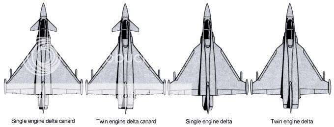
The National Aeronautics and Space Administration (NASA) did considerable work, starting in 1959, on basic configurations for the SST. There evolved four basic types of layout that were studied further by private industry. The aircraft manufacturer Lockheed chose to go with a fixed-wing delta design; whereas another aircraft company, Boeing, initially chose a swing-wing design.

One problem associated with the SST is the tendency of the nose to pitch down as it flies from subsonic to supersonic flight. The swing-wing can maintain the airplane balance and counteract the pitch-down motion. Lockheed needed to install canards (small wings placed toward the airplane nose to counteract pitch down). Eventually, the Lockheed design used a double-delta configuration and the canards were no longer needed. This design proved to have many exciting aerodynamic advantages. The forward delta begins to generate lift supersonically (negating pitch down). At low speeds the vortices trailing from the leading edge of the double delta increase lift. This means that many flaps and slats could be reduced or done away with entirely and a simpler wing design provided. In landing, the double delta experiences a ground-cushion effect that allows for lower landing speeds. This is important since three-quarters of airplane accidents occur in takeoff and landing. The British-French Concorde and the Russian Tupolev Tu-144 prototypes use a variation of the double delta wing called the ogee wing. It, too, uses the vortex-lift concept for improvement in low-speed subsonic flight.

Ultimately, Boeing with a swing-wing design was selected as the winner of the U.S. SST competition. The size of the Boeing SST design grew to meet airline payload requirements. Major design changes were incorporated into the Boeing 2707-100 design. The supersonic cruise lift-drag ratio increased from 6.75 to 8.2, and the engines were moved farther back to alleviate the exhaust impinging on the rear tail surfaces. Despite the advantages previously quoted for a swing-wing concept, technological advances in construction did not appear in time. Because of the swing-wing mechanisms and beefed-up structure due to engine placement, incurable problems in reduction of payload resulted. Boeing had no recourse but to adopt a fixed-wing concept—the B2707-300. Political, economic, and environmental factors led the United States to cancel the project in 1972.

While the British-French Concorde and Russian Tu-144 fly, research is still continuing into advanced supersonic transports in the United States. Whereas, the Concorde and Tu-144 cruise at Mach = 2.2 to 2.4, and the Boeing design cruised at Mach = 2.7, configurations with a cruise speed of Mach = 3.2 have been being analyzed.

Sonic Boom

One of the more objectionable of the problems facing any supersonic transport is commonly referred to as the "sonic boom." To explain sonic boom, one must return to a description of the shock-wave formation about an airplane flying supersonically. A typical airplane generates two main shock waves, one at the nose (bow shock) and one off the tail (tail shock). Shock waves coming off the canopy, wing leading edges, engine nacelles, etc. tend to merge with the main shocks some distance from the airplane. The resulting pressure pulse changes appear to be N-shaped. To an observer on the ground, this pulse is felt as an abrupt compression above atmospheric pressure followed by a rapid decompression below atmospheric pressure and a final recompression to atmospheric pressure. The total change takes place in one-tenth of a second or less and is felt and heard as a double jolt or boom.

The sonic boom, or the overpressures that cause them, is controlled by factors such as airplane angle of attack, altitude, cross-sectional area, Mach number, atmospheric turbulence, atmospheric conditions, and terrain. The overpressures will increase with increasing airplane angle of attack and cross-sectional area, will decrease with increasing altitude, and first increase and then decrease with increasing Mach number.

Turbulence in the atmosphere may smooth the "N" wave profile and thus lessen the impact of the boom or, on the other hand, may in fact amplify the overpressures. Reflections of the overpressures by terrain and buildings may cause multiple booms or post-boom aftershocks. In a normal atmospheric profile, the speed of sound increases with decreasing altitude. The directions in which the overpressures travel are refracted in this normal case and they will at some point curve away from the Earth. The strongest sonic boom is felt directly beneath the airplane and decreases to nothing on either side of the flight path. It is interesting to note that a turning supersonic airplane may concentrate the set of shock waves locally where they intersect the ground and produce a superboom.

Perhaps the greatest concern expressed about the sonic boom is its effect on the public. The effects run from structural damage (cracked building plaster and broken windows) down to heightened tensions and annoyance of the citizenry. For this reason, the world's airlines have been forbidden to operate supersonically over the continental United States. This necessitates, for SST operation, that supersonic flight be limited to overwater operations. Research for ways in which to reduce the sonic boom continues.

—Adapted from Talay, Theodore A. Introduction to the Aerodynamics of Flight. SP-367, Scientific and Technical Information Office, National Aeronautics and Space Administration, Washington, D.C. 1975. Available at cover

Supersonic Flow

=============================================
Theories of Flight - An Overview


During the centuries before the Wright brothers' first flight in 1903, physical scientists had developed a large body of theory concerning fluid flow. Much of their work had focused on understanding the flow of water, and incompressible fluid, and the science of fluid flow was originally called hydrodynamics. Only a small number of these researchers were interested in studying airflow, largely because human flight was believed to be impossible. Yet because air and water are both fluids, some important concepts for the science of aerodynamics came from studies of water.


The first of these was Bernoullli's Principle, which states that in a fluid in motion, as the fluid's velocity increases, the fluid's pressure decreases. Derived by Daniel Bernoulli during the 1730s from an examination of how water flowed out of tanks, this principle is often used (not entirely correctly) to explain how wings generate lift. Because of the way wings are shaped, air flowing across the top of the wing must move faster than the air across the wing's bottom. The lower air pressure on top of the wing generates a “suction” that lifts the airplane. Bernoulli's principle was an incomplete description of how lift works, but it was a beginning.


Bernoulli's student, Leonhard Euler, made what was probably the 18th century's most important contribution to 20th century aerodynamics, the Euler equations. During a 25-year period in St. Petersberg, Russia, Euler constructed a set of equations that accurately represent both compressible and incompressible flow of any fluid, as long as one can assume that the flow is inviscid—free of the effects of viscosity. Among other things, Euler's equations allow accurate calculation of lift (but not drag). The equations were published in a set of three papers during the 1750s and were well known to individuals interested in experimenting with flying machines later in that century, such as George Cayley. Unfortunately, neither Euler nor anyone else had able to solve the equations during the 18th or early 19th centuries. This did not stop theoreticians from continuing to seek yet more powerful analytic descriptions of fluid flows. The key issue missing from Euler's description of fluid motion was the problem of friction, or what modern aerodynamicists call skin drag. During the early 19th century, two mathematicians, Frenchman Louis Navier and Englishman George Stokes, independently arrived at a set of equations that were similar to Euler's but included friction's effects. Known as the Navier-Stokes equations, these were by far the most powerful equations of fluid motion, but they were unsolvable until the mid-20th century.


The unsolvability of the highly complex Euler and Navier-Stokes equations led to two consequences. The first was that theoreticians turned to trying to simplify the equations and arrive at approximate solutions representing specific cases. This effort led to other important theoretical innovations, such as Hermann von Helmholtz's concept of vortex filaments (1858), which in turn led to Frederick Lanchester's concept of circulatory flow (1894)and to the *****-Joukowski circulation theory of lift (1906). (see fig) The second consequence was that theoretical analysis played no role in the Wright brothers' achievement of powered flight in 1903. Instead, the Wrights relied upon experimentation to figure out what theory could not yet tell them.


Experimentation with airfoil shapes had its own long history. Researchers had devised two different instruments with which to conduct airfoil experiments. The earlier device was called a whirling arm, which spun an airfoil around in a circle in order to generate lift and drag data. The second instrument, the wind tunnel, became the primary tool for aerodynamic research during the first half of the 20th century. Invented by Francis Wendham in 1870, the wind tunnel was not initially well regarded as a scientific instrument. But that changed when the Wright brothers used one of their own design to demonstrate that data produced by numerous other respected and methodical researchers using the whirling arm was wrong. The discredited whirling arm vanished as a research tool after 1903, while a vast variety of wind tunnels sprang up across the western world.


After the Wrights' success, theory and theoreticians began to play a larger role in aeronautics. One major reason why was Ludwig Prandtl, who finally explained the two most important causes of drag in 1904. Prandtl argued that the fluid immediately adjacent to a surface was motionless, and that in a thin transitional region (the boundary layer), as one moved away from the surface the fluid velocity increased rapidly. At the edge of this boundary layer, the fluid velocity reached the full, frictionless velocity that researchers had been studying for the past two centuries. Thus the effects of friction, or skin drag, were confined to the boundary layer. Under certain circumstances, this boundary layer could separate, causing a dramatic decrease in lift and increase in drag. When this happens, the airfoil has stalled. Prandtl's boundary layer theory allowed various simplifications of the Navier-Stokes equations, which in turn permitted prediction of skin friction drag and the location of flow separation for simple shapes, like cones and plates. While Prandtl's boundary layer simplifications still did not make calculation of complex shapes possible, the boundary layer theory became very important to airfoil research during the 1920s.


The 1920s also saw the beginning of research focused on what was called the compressibility problem. Because air is a compressible fluid, its behavior changes substantially at high speeds, above about 350 miles per hour (563 kilometers per hour). Airplanes could not yet go that fast, but propellers (which are also airfoils) did exceed that speed, especially at the propeller tips. Airplane designers began to notice that high-speed propellers were suffering large losses in efficiency, causing researchers to investigate. Frank Caldwell and Elisha Fales, of the U.S. Army Air Service, demonstrated in 1918 that at a critical speed (later renamed the critical Mach number) airfoils suffered dramatic increases in drag and decreases in lift. In 1926, Lyman Briggs and Hugh Dryden, in an experiment sponsored by the National Advisory Committee for Aeronautics (NACA), demonstrated that a dramatic increase in pressure occurred on the airfoil's top surface at the critical speed, indicating that the airflow was separating from the surface. Finally, the NACA's John Stack found the cause of this flow separation in 1934. Using a special camera, Stack was able to photograph the formation of shock waves above the airfoil's surface. As the figure shows, the shock wave was the termination of a pocket of supersonic flow caused by the air's acceleration over the airfoil. The shock wave, in turn, caused the boundary layer to separate, essentially stalling the airfoil.


Over the subsequent decades, several individuals found ways to delay and weaken shock wave formation to permit higher speeds. The first of these was Adolf Busemann's 1935 idea of swept wings, initially ignored but rediscovered in the 1940s by Robert T. Jones and now used on all modern jet airliners. During the 1950s, NACA researcher Richard T. Whitcomb developed the transonic area rule, which showed that one could reduce shock strength by careful tailoring of an aircraft's shape. In the 1960s, Whitcomb also demonstrated that one could design an airfoil that could operate well above the critical Mach number without encountering severe flow separation—a supercritical wing.


Supersonics
Long before Whitcomb worked out the supercritical wing, however, the quest for higher performance had led the US Air Force to demand true supersonic aircraft. From the standpoint of aerodynamic theory, supersonics posed an easier problem. On a transonic aircraft, shockwaves formed on top of the wings, meaning that part of the wing had supersonic flow and part of it had subsonic flow—a very difficult problem to resolve mathematically. In supersonic flight, however, the shockwaves formed at the aircraft's leading edges, meaning that the entire airflow around the vehicle was supersonic. This eliminated a large source of complexity. During the 19th century and the first two decades of the 20th century, researchers Leonhard Euler, G.F.B. Riemann, William Rankine, Pierre Henry Hugoniot, Ernst Mach, John William Strutt (Lord Rayleigh), Ludwig Prandtl, and Theodor Meyer had developed a solid methodology for calculating the behavior of supersonic shockwaves. During the 1920s, Swiss scientist Jakob Ackeret, working in Prandtl's laboratory at Goettingen, succeeded in simplifying, this body of theory enough so that it could be used to calculate the lift and drag of supersonic airfoils. Supersonic theory thus preceded supersonic flight substantially.


The major challenge aerodynamicists faced in making supersonic flight reasonably efficient was in finding ways to reduce the one unique kind of drag supersonic aircraft experienced: wave drag. Sonic shock waves were really compression waves, which meant that the air behind the shock was at a higher pressure than the air in front of the shock. The higher pressure behind the shock was exerted directly on the aircraft's leading edges and tended to slow it down—in other words, the higher pressure produced more pressure drag. In 1932, again well before supersonic flight was possible, Hungarian scientist Theodore von Kármán developed a method to calculate wave drag on simple bodies. It could also be used on more complex shapes, but the calculations necessary quickly became overwhelming. Through the 1960s, wave drag calculations for complex aircraft shapes were so laborious they were rarely done. Instead, aerodynamicists involved in supersonic research primarily experimented with wind tunnel models until electronic digital computers powerful enough to do the calculations became available in the 1960s.


Hypersonics
If the challenges of designing supersonic aircraft helped motivate aerodynamicists to adopt the digital computer as design tool, hypersonic vehicles sparked a new subdiscipline, aerothermodynamics. Hypersonic flight, traditionally defined as speeds above Mach 5, meant new problems for aerodynamicists, one of which was the role of heating. At high speeds, friction causes the surface of a vehicle to heat up. At Mach 6.7, the speed NASA's X-15 research aircraft reached in the early 1960s, temperatures exceed 1300° F (704° C). Vehicles returning from space hit the atmosphere at speeds above Mach 18, producing temperatures above those at the Sun's surface. This places enormous heat loads on vehicles that can destroy them if their aerodynamic characteristics are not very carefully chosen.


After World War II, as the United States began to develop rockets for use as weapons and for space flight, the need to design vehicles for heat began to supplant the need to design them for aerodynamic efficiency. The earliest, and simplest, example of how important heating is to hypersonic aircraft design was the late 1950s recognition that for vehicles re-entering the earth's atmosphere, aerodynamicists should deliberately chose aerodynamically inefficient shapes. H. Julian “Harvey” Allen of the NACA's Ames laboratory is generally credited with this realization. Engineers designing missiles in the 1940s and 1950s expected to copy the aerodynamics of artillery shells—cones flying point first—for the missiles' warheads. Allen proposed that this was exactly backward. Warheads could still be conical, but they should fly blunt-end first. Allen based his reasoning on the behavior of shock wave that formed in front of the vehicle. Shock waves dissipate energy, and the stronger the shock wave, the more energy it would dissipate away from the vehicle structure. A pointed vehicle would form a weak shockwave and therefore would experience maximum heating. A blunt vehicle would produce a much stronger shockwave, reducing the heat loading the vehicle had to withstand. In essence, Allen's blunt-body theory required aerodynamicists to discard their long-standing emphasis on aerodynamic efficiency and embrace deliberately inefficient shapes for hypersonic flight.


One unusual concept that emerged from the demands of hypersonic flight was the lifting body—an airplane without wings. In the United States, this idea was first proposed at the same 1958 NACA conference on High Speed Aerodynamics that witnessed presentation of the space capsule idea used by both the United States and Soviet Union for their space programs of the 1960s. A lifting body-based hypersonic vehicle would be shaped like a blunt half-cone, to mitigate heating, and would offer the benefit of maneuverability during landing, something the space capsule couldn't do. During the 1960s and 1970s, researchers at NASA's Dryden Flight Research Center flew a variety of lifting bodies to demonstrate the idea's feasibility, including the one prominently featured crashing at the beginning of a popular television series, The Six Million Dollar Man.


Finally, interest in hypersonic flight has led aerodynamicists to revisit the 19th century's theoretical achievements. Because the Navier-Stokes equations can handle heat-conductive air flows as well as viscous, compressible flows—at least they can if aerodynamicists can find solutions to them—they offer the hope of designing reasonably efficient hypersonic vehicles. During the late 1970s, a new subdiscipline in aerodynamics formed around the use of supercomputers to approximate solutions to the Navier-Stokes and Euler equations. Called computational fluid dynamics, or CFD, the practitioners of this discipline are turning the number-crunching power of supercomputers into a virtual wind tunnel able to fully analyze the aerodynamics of any vehicle, in any speed range.


Computational fluid dynamics is actually a very broad research program encompassing all of flight's speed ranges, from subsonic to re-entry, and because it is relatively recent, it is far from being a completed. But it promises to have its greatest impact on hypersonic flight due to the combination of inadequate test facilities and high design complexity. An example will help illustrate CFD's promise while also underscoring how far aerodynamicists have to go before hypersonic flight is well understood. During the 1980s, the US Air Force and the National Aeronautics and Space Administration ran a program to develop hypersonic vehicle that could replace the Space Shuttle, but would use air-breathing engines instead of rockets. In the early 1990s, however, it became clear that the development effort had been premature. Aerodynamicists did not know exactly how air would behave during a key part of the vehicle's flight. The CFD analysis had produced an answer, but due to the lack of test facilities no one knew whether the computer was correct. If the CFD analysis was wrong, even slightly, the vehicle would not achieve orbit. And at a cost of more than $10 billion, failure due to a lack of basic knowledge was not acceptable to anyone. Hence NASA is currently trying to verify the computer's answer by flying a CFD-designed working model, the X-43A, atop a solid-fuel booster rocket. If the X-43A performs as CFD predicts it will, then aerodynamicists will be one significant step closer to one of aviation's ultimate goals, an airplane that can reach space.


--Eric Conway
Drag
U. S. Centennial of Flight - History of Flight
 
In another variant known variously as compound delta, double delta or cranked arrow, the inner part of the wing has a very high sweepback, while the outer part has less sweepback, to create the high-lift vortex in a more controlled fashion, reduce the drag and thereby allow for landing the delta at acceptably slow speed. This design can be seen on the Saab Draken fighter, the prototype F-16XL "Cranked Arrow" and in the High Speed Civil Transport study. The ogee delta (or ogival delta) used on the Anglo-French Concorde Mach 2 airliner is similar, but with a smooth 'ogee' curve joining the two parts rather than an angle.
EpTud.gif
p331.jpg
p338b.jpg
XvBpSqT.png
BTPqlw1.jpg
ryRFcOx.png
0MLeWn0g.jpg
 
F-18 vs F-16 - A Navy Test Pilot's Perspective

As a Navy test pilot on an Air Force exchange tour, I have the best job in the world: I get to fly the F-16 Viper and the F/A-18 Hornet. Last summer, I completed Viper conversion training at the 310th Fighter Squadron at Luke AFB, and the first thing they teach is the single-engine, single-seat mindset-a new concept for a twin-engine fighter pilot. The Viper has only one engine and pilots quickly learn the "Iguana stare", which is when one eye constantly monitors the engine instruments, and the other scans everything else. Some USAF pilots have labeled the F-16 a "lawn dart", as it has one of the highest accident rates in the Combat Air Force. It's a myth that the high accident rate is caused by the lack of redundancy inherent to a single-engine fighter. The reality is that most F-16 mishaps occur because of factors other than engine failure. Running into things (the ground or other airplanes) accounts for more than three-quarters of F-16 mishaps.

After 50 hours in the jet, I've come to consider the aircraft at least a close acquaintance, and we're working toward becoming good friends. During that time, I've formed some opinions and impressions of the Viper compared with my normal mount: the F/A-18 Hornet.

THE COCKPIT

When compared with the Hornet's, the Viper's cockpit is more compact and is very comfortable. The ejection seat's fixed, 20-degree recline angle is great for all phases of flight except air-combat maneuvering (ACM). During a fight, the pilot has to constantly lean forward to look over a shoulder or check six, and at 7 or 8G, the fixed recline angle produces a sore neck and back in nothing flat. A flight surgeon once told me that 90 percent of all fighter pilots suffer from chronic neck and back pain and Viper drivers suffer the most. The single-piece bubble canopy is one feature that I wish the Hornet had. The glass comes down to the elbows and wraps around the pilot; it provides great six o'clock and over-the-nose visibility without a canopy bow or heads-up-display (HUD) post to obstruct the view.

The main instrument panel is centrally located, compactly organized and easy to scan. The Viper is a fly-by-wire electric jet, but it still has what are considered old-fashioned, round airspeed and altitude dials, tape gauges for vertical speed indicator (VSI) and angle of attack (AoA) and an analog attitude indicator. These are the primary flight instruments because the HUD is technically not certified for IFR (instrument flight). In the Hornet, I use the HUD as my main information source and crosscheck the steam gauges during instrument approaches. The Viper HUD gives the same data as the Hornet HUD does, but the format's different. Adapting was easy except for one important item: the angle of attack bracket. The two indicators look exactly alike, but they work exactly opposite; when landing, one tells the pilot to pull when he should push, and vice versa. It's potentially very confusing. Flying AoA "backward" was tough at the beginning, but I eventually figured it out. The rest of the Viper's HUD symbols are busy but easy to interpret. By flipping a few switches, the pilot can customize HUD information as needed for the mission.

The Viper's side stick and throttle are marvels of ergonomie design. For single-seat strike fighters without the benefit of a guy in the back (GIB) to operate the radar and weapons systems, the hands-on throttle and stick (HOTAS) design is key to managing the airborne workload. As its name implies, HOTAS allows complete pilot control of the weapons systems with hands-on maintenance of the flight controls. The Viper has 16 HOTAS controls, and all are easily actuated with minimal movement. Some of the "HOTAS-able" functions include: radar mode select, bomb pickle, gun trigger, missile pickle, chaff/flare dispense, etc.

The throttle designator control (TDC) is a feature that's found in both aircraft, and it's essentially the "mouse" of the weapons system. It's used for slewing the cross-hairs over targets detected on the radarscope or in the HUD and locking onto them. The Viper's TDC is on the throttle under the left thumb; it took some getting used to for making fine-tuning adjustments. The Hornet's TDC is a little easier to use because of its location under the left index finger. I have much more dexterity with my index finger and found sensor slewing much easier in the Hornet.

In the Viper, all radar and targeting forward-looking infrared (FLIR) pod information is presented on the two monochrome multifunction displays (MFDs). They are smaller and are of older technology than the Hornet's, but the displays are easy to read in all lighting conditions. The F/A-18 has three color MFDs with the center one being a larger digital moving-map display. The moving map, or multipurpose color display (MPCD), is the key feature that distinguishes the two strike fighters. The sheer amount of situational awareness that the Hornet's MPCD provides the pilot of threats, friendly locations, geographic references and navigational data significantly enhances combat effectiveness. Without the moving-map display, the pilot's mental workload doubles, and some of the more senior pilots, including myself, will "down" the aircraft and not fly it if the map display fails. Some newer block Vipers have display upgrades that mirror the current capability of all Hornets, but those are exceptions. Avionics in the Hornet are far superior to those found in almost anything I have flown. The one exception is the Super Hornet; it has two additional displays that improve on the Hornet's design.

The F-16 consoles aren't as well organized as the Hornet's; some switches are hard to reach. For the most part, that doesn't affect normal operations but could delay pilot reaction time during an emergency. For example, the Viper's throttle obstructs access to the engine control switch with afterburner selected. This switch is used to back up the electronic engine control during certain failures; reaching around the throttle could delay completing the critical action procedures if the engine gets sick right after takeoff.

The Hornet's consoles are logically grouped by systems. The environmental control system control panel, electrical control panel and lighting control panel are separate units. Conversely, the Viper's left console has flight-control switches mixed with the electrical switches and fuel transfer switches; they're clustered together. After about a dozen simulations and flights, I was able to adapt to the F-16 normal and emergency procedures checklists, but the Viper's cockpit layout appears to be a product of evolution, whereas the Hornet's cockpit layout has changed little since day one.


SIDE STICK VERSUS CONVENTIONAL CENTER STICK

Both the Hornet and Viper use fly-by-wire flight-control systems, which means aircraft response is governed by a set of programmed flight-control laws that "live" in the flight-control computers, which I affectionately refer to as "George". In other words, the pilot isn't flying the airplane, George is. The pilot tells George he wants the airplane to do something, and George then zips through the math to figure out which flight-control surfaces should be moved to fulfill the pilot's request. The big difference (and it is a big one) is that the Hornet uses a conventional center stick, and the computer senses stick position to interpret what the pilot wants. The Viper uses a side stick, and the computer senses stick force from pilot input.

Flying a side-stick control takes a while to get used to, but once you do, it's a joy. The conformal stick's shape feels very natural (it fits in the hand like a melted candy bar), and it allows easy access to nine of the 16 HOTAS controls. Two fully adjustable forearm rests on the right cockpit bulkhead stabilize and isolate the pilot's arm and wrist, so when rattling around the cockpit during turbulence or going after the bad guy, the pilot's arm won't accidentally move and initiate unwanted control inputs. In its original design, the Viper's control stick didn't move at all; it just measured pressure from the pilot's hand. However, after initial F-16 flight tests, a ¼ inch of stick movement was incorporated to give a small dead band and a nominal breakout force to give better "feel" of a neutral stick because otherwise it was entirely too sensitive. The control harmony is quite good (the pressures required for pitch and roll mix well), but without the capability to physically position the stick, it's easy to contaminate roll inputs with unwanted pitch inputs, and vice versa.

My first Viper instructor predicted that I would over-rotate on takeoff and drop the right wing; he was right. The over-rotation occurs because a pilot is used to "moving the stick and then something happens" at rotation speed. When I reached 145 knots and pulled back, of course the stick didn't move but a scant ¼ inch, so I pulled more. The inexperienced have no way of knowing how hard to pull, so I pulled probably twice as hard as was necessary. After a half-second delay, the nose abruptly responded to my input and pitched up to about 10 degrees, while at the same time the right wing dipped to about 10-degrees wing down. I released back-stick pressure, and the aircraft held 10-degrees pitch as I gently leveled the wings. According to my instructor Lt. Col. Dan Levin, who has more than 3,000 Viper hours, pilot-induced-oscillations (PIO) are very common on takeoff for transition pilots.


TAKEOFF PERFORMANCE

In my opinion, the Viper's biggest strength is its brute force: it has lots of horsepower. The biggest kick in the pants-next to a catapult shot off an aircraft carrier-is the kick from stroking full afterburner in a General Electric-powered, bigmouth Viper on a cold winter morning. With a greater than 1.2:1 thrust-to-weight ratio at takeoff gross weight, it takes all of 1,200 feet to get airborne at 160 knots, and the jet can be supersonic just two miles later, if it's left in burner. The acceleration is unbelievable! If there weren't a 7G restriction on a fueled centerline tank, I would easily have 9G available to pull straight into the vertical and accelerate on the way up. Of course, I've done the "quick climb" to 15,000 feet, and after level-off, I still have 350 knots. The Viper can out-accelerate most anything in the air, including the Hornet.

To accurately compare the Hornet's performance to the Viper's, I took off from the same runway. The Hornet needed 200 feet more than the Viper to get airborne at about the same speed, and at the end of the runway it had only 330 knots versus the Viper's 500-plus. The best climb angle that I could get out of the Hornet before airspeed started to decay was 45 degrees, and I leveled off with 200 knots; the Viper's climb took one minute less. The Hornet's lack of thrust seems to be where all the critics linger, and that's valid-to a point. When a pilot flies into battle, lots of thrust is nice to have and is definitely fun to have, but it isn't necessarily a must-have-depending on the aircraft's other attributes. Like the Viper, the Hornet has different engine versions in inventory, but even with two "big motors", the GE-404-402 has 18,000 pounds of maximum thrust each, and in a drag race, the Hornet would be no match for the Viper.

When the wheels are in the well, the Viper flight controls change from takeoff and landing gains (it automatically changes modes, as it requires different pressures for the same reaction) to cruise gains. This reduces the PIO tendency in pitch when the aircraft is slower and near the ground. The acceleration in after-burner seems to build with airspeed, and it's really a kick! The faster I go, the faster I go; this is primarily because of the fixed-geometry inlets that become more efficient as airspeed increases. Canceling afterburner (AB) at 300 knots and 2,000 feet AGL does not stop the amazing acceleration. Even in military power, the Viper easily slips above the 350-knot climb speed in a 15-degree climb. On the other hand, the Hornet has a smooth and steady acceleration and quickly reaches the standard climb profile of 300 knots in a 15-degree climb at military power. In the Hornet, the nose must be lowered to about 5 degrees at 10,000 feet for it to accelerate and maintain a 350-knot climb speed.

Once in the air, the Viper pilot can drill around all day at 350 to 400 knots and still have fuel to spare. If there's a concern about fuel conservation, the Hornet works best in the 300- to 350-knot speed regime. Roll performance in the Viper is slightly faster than the Hornet's. A full-deflection aileron roll is eye watering in a clean Viper (about 360 degrees per second) and very impressive in a slick Hornet (about two-thirds the speed of a Viper). One nice feature of the side-stick controller is the capability to rapidly capture a precise bank angle by simply releasing the stick. The jet's controls essentially freeze when the pilot lets go of the stick, even when whipping around at maximum rate roll. This is real handy in rolling in on a target (both air-to-air and air-to-ground). The Hornet's roll control is equally precise, but it requires a bit more finesse. Its flight-control system in cruise is a "G-command" flight-control system; it continuously trims to 1G flight regardless of aircraft attitude. If a pilot rolls inverted in a Hornet and let's go of the stick, the jet "pulls" 1G and enters a gradual dive to maintain 1G. Doing the same in the Viper causes the pilot to get light in the seat; the jet doesn't feel any pilot input, so it continues to head straight and inverted. The Hornet's G-command has bitten a few transition pilots during ACM when they were confronted with very nose-high, low-speed attitudes. Tomcat drivers learning the Hornet typically release the controls, as that is what they were used to doing in the F-14, which stops flying around 100 knots. In the Hornet, this just leads to a further nose-high attitude, as the Hornet reverts to pulling and placing 1G on the airplane.

The Viper rolls well, but it is easy to inadvertently add G during rolling maneuvers because it takes some concentration to prevent accidentally applying back stick pressure while exerting side pressure in for the roll. I encountered this early in my training. It was challenging, at first, to perform a pure, constant 1G maximum-rate aileron roll: nose up and then fly a gentle arc up and then down while rolling so the seat of my pants stays in the seat all the way through. My tendency was to load the roll to 2G halfway through by applying too much backpressure. The next time, I overcompensated and got light in the seat, as I saw about O.5G. Again, the learning curve is steep; eventually, I could max-perform in roll without inadvertently pulling or pushing G.

In the beginning of the training, it's difficult to yank the nose around in a minimum-radius, maximum-G level turn without accidentally introducing aileron in it that isn't wanted. On my first few attempts at a 9G level turn, I tended to ratchet the wings back and forth from one bank angle to another. The side stick feels only the first 25 pounds of pilot input in the longitudinal axis, at which time it gives all 9G (or whatever's available at that speed). Apparently, I must have also inadvertently applied a small amount of lateral-stick force, and that caused unintended bank-angle changes and the subsequent ratcheting. After a few more tries at a 9G level turn, I learned that by using a smooth, gradual G buildup and by toning down the amount of pull, I could nail a 9G, 360-degree turn while maintaining constant altitude within 100 feet.

This jet can hurt you because it has absolutely no problem holding 9G, especially down low. The Hornet is limited to 7.5G by the flight-control software, even though the airframe can handle 9G; in fact, some foreign versions were going to be sold as 9G jets. The tradeoff is fatigue life. When dogfighting in a Hornet, I rarely see 7.5G, and if so, it's momentary because I'm usually closing to guns after the second merge and am trading airspeed for nose position.


SLOW-SPEED CHARACTERISTICS

There's no better performing fighter in the close-in, slow speed, knife-in-the-teeth dogfight than the F/A-18 Hornet, except maybe, of course, a Super Hornet. But that's another story. The Hornet flies very comfortably at AoAs of up to 50 degrees and has great pitch, roll and yaw authority between 25 degrees of AoA and the lift limit of 35 degrees of AoA. Most crowds are amazed when the Blue Angels perform the Hornet low-speed pass, which is around 120 knots and only 25 degrees of AoA. There are no nasty departures to worry about, and if the pilot happens to lose control, the best recovery procedure is to grab the towel racks (two handgrips on the canopy bow used during cat shots). On the other hand, a Viper has a 25-degree AoA limiter built into its software, and even fewer degrees of AoA are available if it's carrying air-to-ground goodies on the hard points. Up against the limiter, the nose stops tracking; in that case, it's time to drop the hammer and use the big motor to get the knots back, which by the way, happens in a hurry.

The Hornet, however, will stand on its tail, hold 100 knots and 35-degrees AoA and swap ends in a maneuver called "the Pirouette", which looks like a jet fighter doing a hammerhead with a quarter roll. To the spectator and the participant, it looks and feels impossible. The Hornet gets slower (high-energy bleed rate) quicker than anything I've flown, and it gets faster (low acceleration performance) slower than anything I've flown. In a Hornet, it's difficult not to get the first shot in a close-in dog-fight that starts from a perfectly neutral merge (going opposite directions at the same altitude). My Viper buddies tell me there is very little room for error when they fight the Hornet. The best way to handle the situation is to get the Hornet to slow down, while they maintain energy so the Viper's superior thrust-to-weight will out-zoom the Hornet and then they can shoot at it from above. As a Hornet driver, I have never lost to a Viper guy that I saw, but I have run into Viper drivers that said the same thing about their jet.


LANDING

As I dirty up for landing (lowering the gear handle is the only pilot action, all other configuration changes are automatic), the Viper becomes a blended-rate command, AoA-command flight-control system. I can trim the aircraft hands-off to the approach AoA of 11 degrees, and the flight-control system should maintain that AoA. In my experience, the Viper is very pitch-sensitive-especially in the flare.

Landing the Viper is easy, but landing the Viper while making it look good is far from easy. The airspeed is controlled with the throttle, and the glideslope is controlled with the stick (at least on the front side of the power curve). The pilot must use the throttle very judiciously on final; with the huge General Electric motor, it's easy to gain excess airspeed rapidly and then float a quarter mile down the runway. If the pilot misjudges and gets slow, he can scrape the tailpipe or prang the landing gear, with a bounce back into the air below flying speed (very bad).

The Hornet, by contrast, is very easy to land. The aircraft is trimmed for on-speed, and the glideslope is flown with the throttles until touchdown at 650 to 700fpm. Both aircraft have a HUD flight-path marker (FPM) to tell the pilot where the jet is going. The pilot places the FPM on the piece of runway he wants to touch down on, and that's where he'll land. In the Hornet, the throttle is the primary control for the FPM; in the Viper, it's the stick. The vertical-G load on an average trap at the boat is about 2.7G. The longitudinal deceleration from grabbing an arresting cable is about 4G. That landing is actually a precisely controlled crash. It's easy to nail the glideslope in the twin-engine Hornet by adjusting one throttle at a time by "walking the throttles". Precise glide-slope control is really handy when landing on the boat. As a Navy carrier pilot, I'm not the best at flaring the Viper; I usually bounce once or twice, which I'm told isn't bad.


CONCLUSION

I am often asked, "Which one do you like the best?" The answer is easy, and I reply with this analogy: the F-16 Viper is like the Dodge Viper, and the F/A-18 Hornet is like a Lexus. If I want to cruise around town and experience pure acceleration performance, I would drive the Viper. If I want to cruise in total luxury on a long road trip with all the amenities and Gucci displays, I would drive a Lexus.

It's definitely more fun to fly the Viper, but the Hornet is the aircraft that I would want to take into combat. The primary deciding factors are the superior ergonomics in the Hornet's cockpit design, and its avionics controls and displays. The only jet that I've flown that is better is the F/A-18E/F Super Hornet. Another major consideration is the Hornet's capability to take a surface-to-air missile (SAM) up one tailpipe and still make it home on the other engine, as was demonstrated in the 1991 Gulf War.

Speed is nice to have, and I wish the Hornet had more, but my confidence in the jet that I grew up in is high. However, the more exposure I get to the various Viper upgrades and different blocks, the more I appreciate its capabilities. The real bottom line is this: if I were a bad guy, I would hate to go up against either one.


BY LCDR JOHN "TOONCES" TOUGAS
 
DjPSE.jpg


Any idea about the JF 17 wingloading?. been looking for it for 2 years... a ground attack role is better to have a higher wing loading -
low wing loading is for performing at higher altitudes---multirole aircraft has to find a proper balance... would be interesting to know jft's


I was under the wrong impression that the jft design is actually a 2nd gen design , which was slightly updated , but having severe aerodynamic deficienies ...... this aspect had started to plague the thoughts of meny pdf members aswell

i was concentrating on the design evolution or lets say different schools of thought to stabilize the wing at high alpha , vortex generation/ fuselage lift---e.g double delta, lerx, levcon, canard fixed/movable


The tailplane serves three purposes: equilibrium, stability and control.

F-16 / f14 use ventral fins to improve lateral stability whereas in F-15/ F-18 dorsal and vertical fins are enough

Slats/Leading edge Flaps increase the coefficient of lift-increase the maximum AOA during low speed

LERXes improve AoA handling

The F-18 has a very low swept wing which gives excellent lift at low speeds and requires less pitch , AoA to achieve lift.The best wing for low speed is not highly swept, but moderate/low swept...most combat is in that region e.g f-18


dfJJL.jpg
pyjNv.jpg


uNily.png
s1yrB.jpg


Aerodynamic improvements produced by leading-edge flap and forebody strake/lerx on f16
fig088.gif
fig087.gif
xEYxD.jpg

based on the design of wings the jft aoa seems better than f16 and closer to the f18 which is famous for its aoa --- [prominent lerx/strakes---> upto 50% increase in max lift + low/moderate swept wing --> spin resistance]


LERXs & Canards, both basicly both generate vortices and add lift ahead of the center of gravity

Low aspect delta wing and High aspect canard configuration obtains the less drag and good lift-- thus used mostly in such designs , primarily for flight performance -- High lift on canard reduces its efficiency, increasing its efficiency reduces its lift.
 
Trade-off between thrust/weight ratio and wing loading in the air combat and strike roles. Full afterburning and internal load are assumed in each case.
4wxTm.gif


High lift-induced drag of delta wing. Low aspect ratio and loss of lift due to trimming result in a glide ratio of only 3.7 at 1.4 times stalling speed (in landing configuration).
qqTXi.gif


F-16E flying qualities compared with those of the F-16A. Lateral/directional stability is improved; external loads do not adversely affect flying qualities: there are no limitations due to buffet, wing rock, nose slice, deep-stall trim points, or spin tendency; there are no limits on angle of attack, minimum speed and bank angle; and the full range of manoeuvres can be performed while carrying the maximum load of air-to-ground stores
mv2gu.gif


R1oOe.jpg


Effect of hybrid wing and variable camber on maximum lift.
peupI.gif

Effect of hybrid wing and variable comber on drag-due-to-lift at Mach 0.8
3tA7I.gif
 
Effect of hybrid wing on lateral control effectiveness at Mach 0.2
Mbavt.gif


Wobek.gif
Fie93.gif


xnusO.gif

Intake operating conditions
bYw4r.gif
UIFAK.gif
Wq0sO.gif
tJ6Bx.gif

Fuselage boundary-layer removal on Northrop YF-17.
 
bZzIu.gif
UH6yf.gif


Northrop YF-17/McDonnell Douglas F-18 To optimise its turning capability at supersonic speeds the YF-17 was area-ruled specifically to minimise drag-due-to-lift. With the emphasis on Mach 1.2, extensive wind-tunnel testing was carried out to establish the fuselage cross-sectional area both above and below the wing in {159} the manner proposed by Lock and Rogers.18 The area distribution was carefully tailored to create favourable lift interference (i.e. increased lift a! a given AOA). This was done, as shown in Fig 169. by;
1 Significantly reducing the upper-fuselage cross-sectional area forward of the wing to the mid-chord position. This waisting was additional to that applied for zero-lift drag area-ruling.
2 Increasing slightly the lower-fuselage cross-sectional area from the wing leading edge to the trailing edge (see Fig 164).
This differential area-ruling is compared in Fig 169 with that employed on the F-5 to reduce zero-lift drag and to improve transonic acceleration. The favourable lift interference created by differential area-ruling reduces the AOA required to achieve a given lift coefficient, thereby reducing the drag-due-to-lift at the cost of a small penalty in zero-lift drag.
A 5% increase in sustained turn rate at Mach 1.2 resulted from the drag reduction. The differential area-ruling also generates favourable pitching moments which reduce trim drag. The combined benefits of differential area-ruling helped to expand the sustained turn rate envelope above Mach 0-8.
Another aspect of area-ruling shown clearly in Fig 169 is the positioning of the canted twin vertical stabilisers well forward of the horizontal tails, which helps to fill a dip in the area-distribution curve.

General Dynamics F-l 6 The philosophy behind the use of area-ruling on the F-16 had three aims;
1 To minimise the drag of each component by keeping thickness/chord ratios low and fineness ratios high.
2 To minimise adverse interference and maximise favourable interference through judicious placement of major components.
3 To shape components locally, only where absolutely necessary, to alleviate any adverse interference which would otherwise exist.
Principles 1 and 2 are illustrated in the YF-16 normal area curve (Fig 170). The teardrop canopy is placed forward on the fuselage, minimising its large protuberance effect, with the air inlet placed so as to offset the aft-facing slope of the canopy. The strake/shelf is shaped to relieve the forward and aft slopes of the wing respectively. The horizontal and vertical stabilisers are staggered, thus avoiding the simultaneous buildup of their leading-edge area gradients.

Some small changes in the area distribution were made late in the YF-16 design process, creating a small but significant fuel volume increase. The aft fuselage just ahead of the nozzle and shelf, housing the horizontal tail actuator, were trimmed to reduce the drag of the aft-end components and the interference between them. The increases ahead of and behind the wing were adjusted to improve the Mach 1.2 oblique area distribution, though not at the expense of the Mach 1.6 distribution.


ve9rB.gif

JTzqY.gif


How careful empennage design avoids fin/rudder blanking at high angles of attack.
Examples of aircraft with exceptionally good spin recovery are the Lightning, Hawk, F-5 and F-18. On these aircraft the rudder is in clean air even at very high AOA. Some inertially slender aircraft are however designed to use roll control rather than rudder for spin recovery; in such cases the rudder may be immersed in tailplane wake at high AOA with no untoward consequences.
QIRUB.gif
 
Automatic Engine Inlet Guide Vanes (or Canards) are a must on all fighters capable of supersonic flight......however a Canards on the airframe has its pros and cons.

In my opinion its just another thing that could go wrong where the pilot has no direct control over it......with that said it has been used on fighters with success.
 

Latest posts

Back
Top Bottom